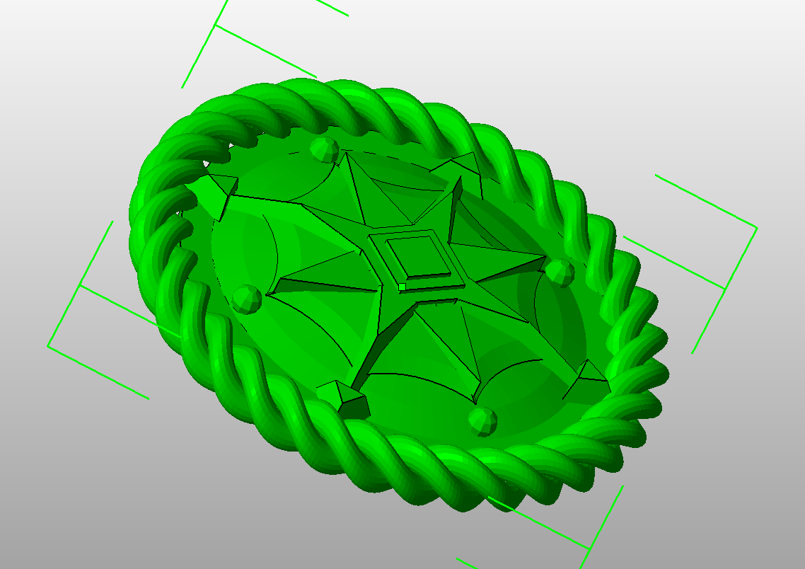
I was contacted by a silversmith recently, that was in the process of making
a batch of buttons for some seafarers.
He gave me this sketch, that the sefarers had given him:
The sketch.
In addition, I got instructions to put a rope ring around the button
to protect from the pointy arrows.
The special challenge for me in this was the scale.
The button was to be produced with two different diameters: 15 and 20 mm.
Height: 1 to 3 mm.
In other words, the details need to be less than 0.33 mm high, and sometimes
ca 0.3 mm wide.
First thing I did was to order a 0.3 mm nozzle from Emakershop.
Second was to make a Git repo which can be found
here.
Wish I had more time to describe the process, but a picture of todays prints
have to do for now.
Initial shot at cadding the button. Revised twice today.
A version of the button with thicker middle part and somewhat
more pronounced details, since the first print turned out too thin and
with too low resolution.
A version of the button with more pronounced details, since the second
print turned out to have too blurry details.
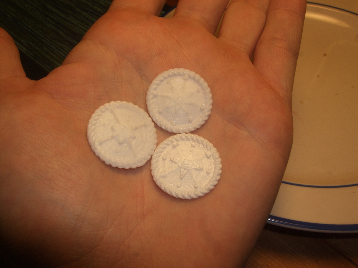
First three (finished) tries at printing the 20 mm version of the buttons.
Another pic of the same three buttons.
- tobben
Torbjørn Ludvigsen
I was contacted by a silversmith recently, that was in the process of making
a batch of buttons for some seafarers.
He gave me this sketch, that the sefarers had given him:
A Cumbersome Beautiful Way of Creating Signs in OpenScad
6-10-2014
I needed a new sign on our mailbox outside our house recently, so I thought I
might as well make a two colored plastic sign this time, since the paper ones
only seems to last for one year or so. If the plastic sign can be used for more
than 10 years, this project might even be a net time saver.
I have made models with letters in them several times, and every time I have ended
up doing it differently. This time, I found a little
Python script,
called font2openscad, that converted True Type Fonts into OpenScad-importable dxf-files.
I wanted to use the letters one at a time, so I wrote a little module:
And then imported just the letters I needed one by one, like this:
T = 11.83;
o = 13.77;
r = 11.73;
b = 10.09;
j =  6.73;
oe= 14.94;
module tbear(){
  letter("font/T.dxf",0);
  letter("font/o.dxf",T);
  letter("font/r.dxf",T+o);
  letter("font/b.dxf",T+o+r);
  letter("font/j.dxf",T+o+r+b);
  letter("font/oslash.dxf",T+o+r+b+j);
  letter("font/r.dxf",T+o+r+b+j+oe);
  letter("font/n.dxf",T+o+r+b+j+oe+r);
}
To find reasonable letter-widths (the T+o+...-part) I used what I found in the
font.scad file created by the font2openscad script.
Using the letters one by one gave me two advantages
The opportunity to make the sign more beautiful by translating each letter manually. (Extremely time consuming of course.)
Avoiding OpenScad messing up Scandinavian letters.
I only exploited the first point only a couple of times as it was too fiddly to be fun.
The second point, however was a huge win. Every letter in the ttf-file imported gracefully
without OpenScad ever getting the chance to mess up while encoding/decoding them.
I am aware that OpenScad has added support for Unicode and that they are adding
native support for extruding text (look
here),
so the method I'm describing in this blog post is mostly relevant for old OpenScad builds
like my own.
The complete script for creating my little mailbox sign can be
found
here.
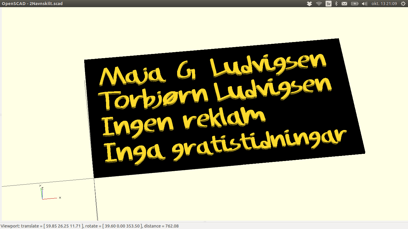
A render of it looks like this:
The sign on my mailbox, built and rendered in OpenScad, one letter at a time.
Getting a Two Color Print With One Bowden-fed Print Head And Monochrome Filament
To get the sign out in two colors, I wanted to pause the print exactly when the last
rectangular layer was done, before starting on the letters. I wanted this pause, so
I could change filament manually because I use a rather long Bowden tube.
I knew I used 0.2 mm z-lift, 0.3 mm layer height and that the rectangular base
was exactly 1.5 mm thick, so to find the critical moment in the gcode was just a matter of
searching for G1 Z1.8000. I then inserted directly into the gcode
commands to
Retract 1 cm filament (G1 F3420.000 E...)
Make a 2 cm z-lift (G1 Z... F10200.00)
Pause SD-print (M25)
Set extruder coordinate to whatever it should be when the manual filament-switch is done and print is resumed (G92 E...).
(Replace ... with values relative to context in gcode.)
Throwing in an SD-pause directly into the gcode like this was rather naïve, as
Marlin does some buffer magic so that the pause aren't guaranteed to happen
at that exact line. In my case, the printer ran two more lines of code before
pausing. This was no problem however, since I could rewind the print, that is
reset the file pointer manually with M26 (set SD position).
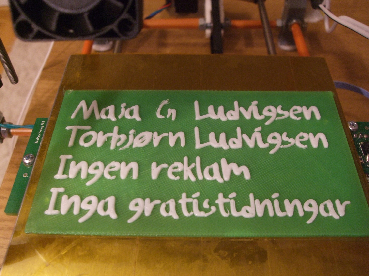
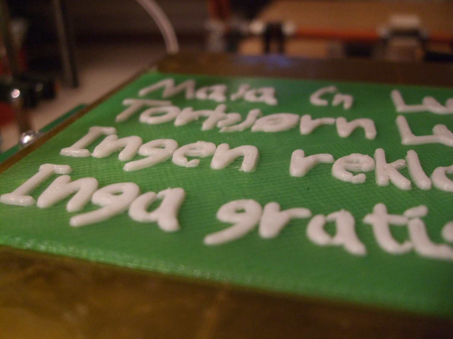
Anyway, here's how the end result looked like:
The sign on my mailbox, printed and ready.
Close up showing print quality, or lack thereof.
It's surprising how fun a simple sign can be when I really should be studying ;)
- tobben
Torbjørn Ludvigsen
I needed a new sign on our mailbox outside our house recently, so I thought I
might as well make a two colored plastic sign this time, since the paper ones
only seems to last for one year or so. If the plastic sign can be used for more
than 10 years, this project might even be a net time saver.
Combining STLs and removing internal faces with Meshlab
12-9-2014
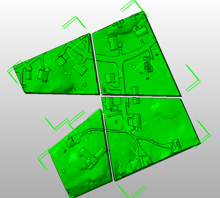
I needed to glue together some stls recently, that fit together like the pieces in a puzzle. Like this:
The four .stl files I needed to merge into a single one.
In short, I wanted to snap the right walls together and remove the resulting double internal faces.
The screendump is from Netfabb Basic,
but it won't let me "merge selected parts" because I don't have a "pro-licence".
So I found a tip here
here
that I used with some modifications.
First, I imported all the meshes into Meshlab and flattened the visible layers. This
gives me all the parts in a single mesh. I then gave all faces "quality numbers"
based on how visible they were. This made it possible to select the internal faces
only and delete them.
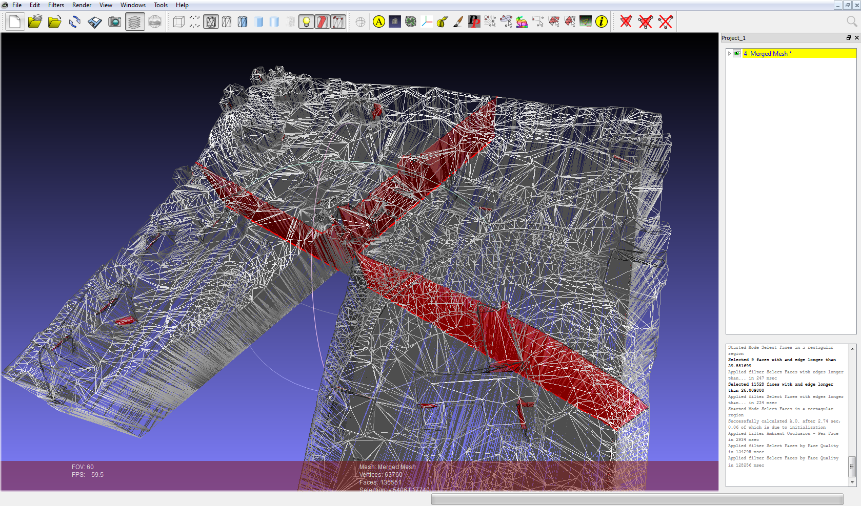
The sequence of Meshlab commands was
Filters -> Mesh Layer -> Flatten Visible Layers Filters -> Color Creation and Processing -> Ambient Occlusion - Per Face Filters -> Selection -> Select Faces by Face Quality.
With min=0 and max=0.05 I got this selection:
The selection I got in Meshlab when searching for the least visible faces.
If you look closely, you see that some internal faces in my buildings are also selected.
Those are also unwanted, so getting them selected is like an extra bonus =)
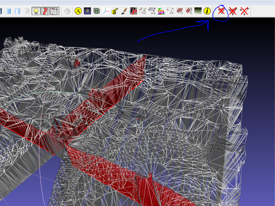
Button in Meshlab to delete selected faces.
That did the trick for me. Hope it does for you to ;)
- tobben
Torbjørn Ludvigsen
I needed to glue together some stls recently, that fit together like the pieces in a puzzle. Like this:
Explanation of basic RepRap mechanics (Swedish)
12-8-2014
I crawled the web after an image of me and a 3d-printer today, to use in an article about the Martineåsen Project in the local
newspaper. Surprisingly I stubled upon an old video of myself, from another newspaper. You need a paid membership to see it,
so i put it here.
(Warning from the future (2020). The video had moved, and the new player might show ads before playing the actual video.)
- tobben
Torbjørn Ludvigsen
I crawled the web after an image of me and a 3d-printer today, to use in an article about the Martineåsen Project in the local
newspaper. Surprisingly I stubled upon an old video of myself, from another newspaper. You need a paid membership to see it,
so i put it here.
The Martineåsen Project
8-8-2014
The start of it
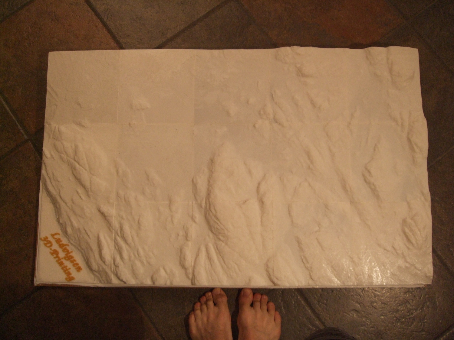
I received a call recently, from the Geo-data department of the municipality.
They were developing some new housing in Martineåsen, and wondered if I could
print it for them, scale 1:2000. It turned out my dad had tipped them about my
RepRapping. I printed them a test piece and dad talked me into promising them
fifteen pieces of landscape prints,
each of them maximizing the print area of Gomle
(19 x 19 cm). I thought the project was total madness right from the beginning.
This would be an order of magnitude bigger than my most complicated print
thus far, and it was to be done with the most unstable printer I've ever built,
having access to two old laptops as my only computing power.
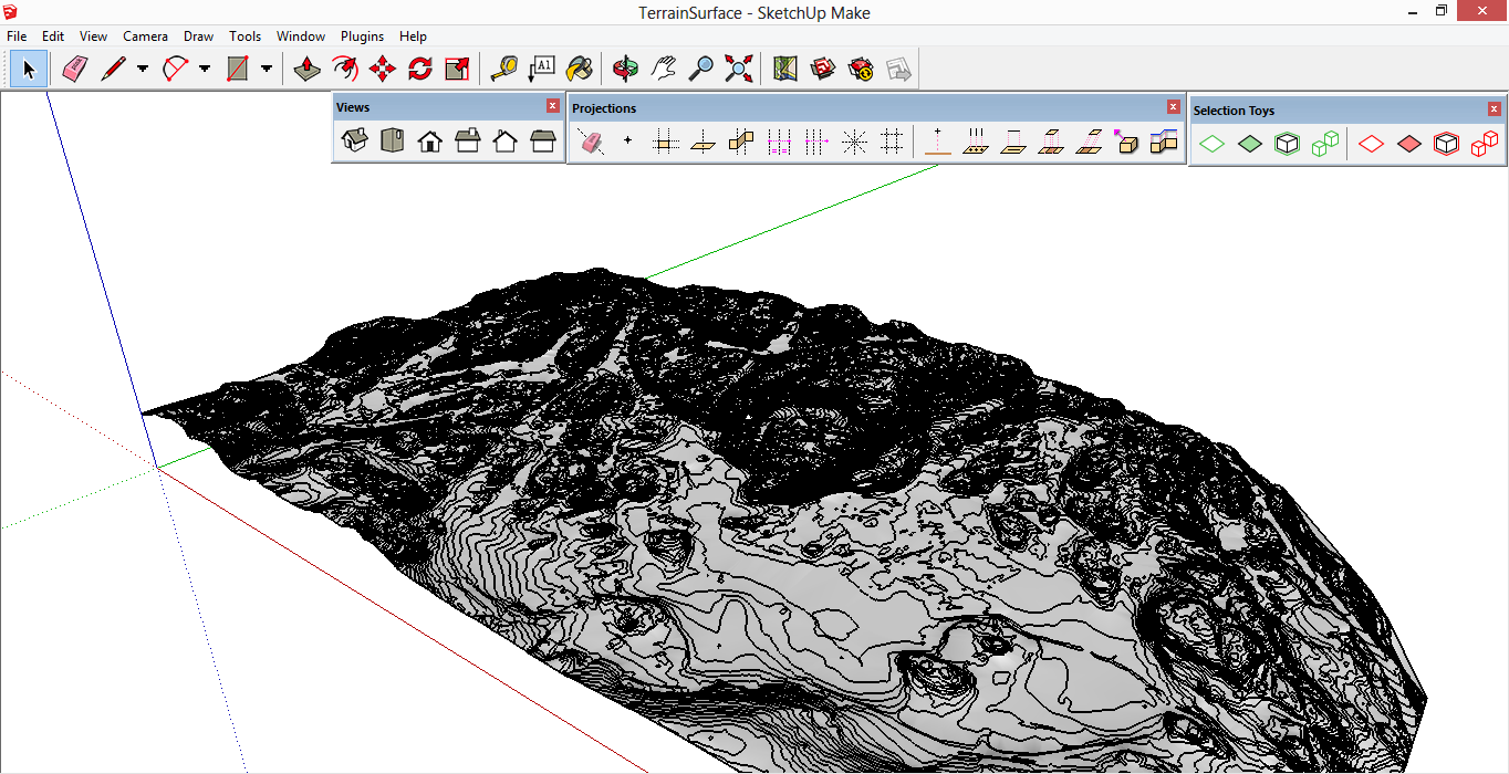
Creating a 3D model from contour lines
I didn't have access to any licenced 3D software what so ever, so I tried various
free alternatives and started to have some limited success with Google SketchUp.
I won't go into details here, but it turned out that creating the surface was
really trivial (although computationally intensive). Looking around in the menus
I found Draw->Sandbox->From Contours which transformed my contour data
into a surface. Perfect.
Surface created from the dxf file I got from the customer.
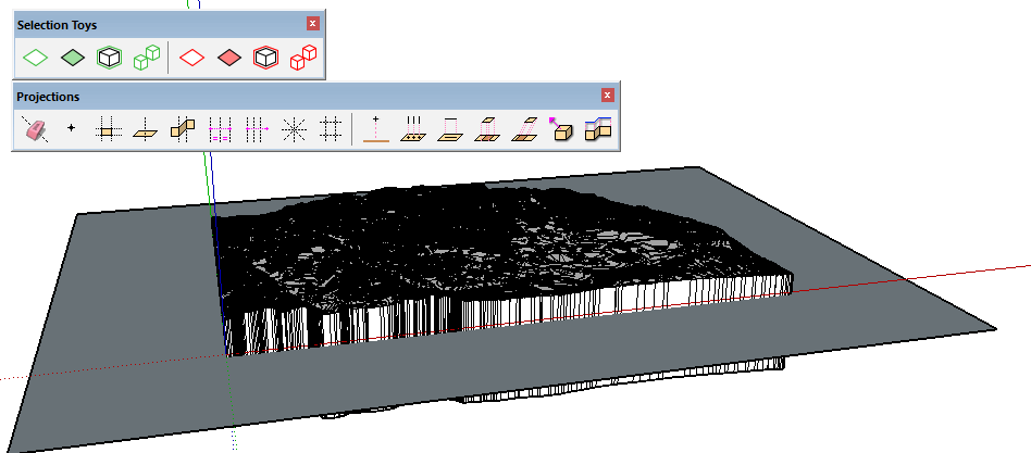
However, to create an stl, you need a watertight model, not just one surface,
so I needed to build walls and floor myself. Easy peasy was my first thought.
It took me five working days (well, most of the time I were just waiting for my
dads poor laptop to finish processing/rendering). I won't go into detail here,
but the solution involved Simplify contours plugin, Projections plugin,
Selection toys and Intersecting surfaces.
My recommendation is: don't ever try to process large map data files with
SketchUp and an old laptop. It doesn't work well.
Making walls and floor for my stl model of Martineåsen.
Everything crashes
I managed to get out two pieces, looking roughly the same as the demo print.
The demo print that convinced the Geo-data department I could print
Martineåsen.
Then lightning struck and destroyed my FTDI-chip! Luckily, I had a new Melzi
circuit board lying around. I carefully moved all wires from the old Melzi to
the new Melzi, uploaded firmware to the new board and everything seemed jolly
good again. Then I suddenly lost contact. I unplugged and replugged the USB, and
guess what? My laptop processor was suddenly toast! My new circuit board transformed
my beloved laptop into a sad piece of molten plastic! Some of the following
debugging is described here.
The mistake was my own. I had not attached the minus side of the 12 V power chord
tight enough.
Everything just works
When the hiccups of my new board was ironed out, the following 13 pieces printed
more or less smoothly. Each peace took ca 12 hours to print, so my dad took the
time to learn how to make time-lapse videos while waiting. This is the next last
piece printing:
We also made a time-lapse of the mounting process:
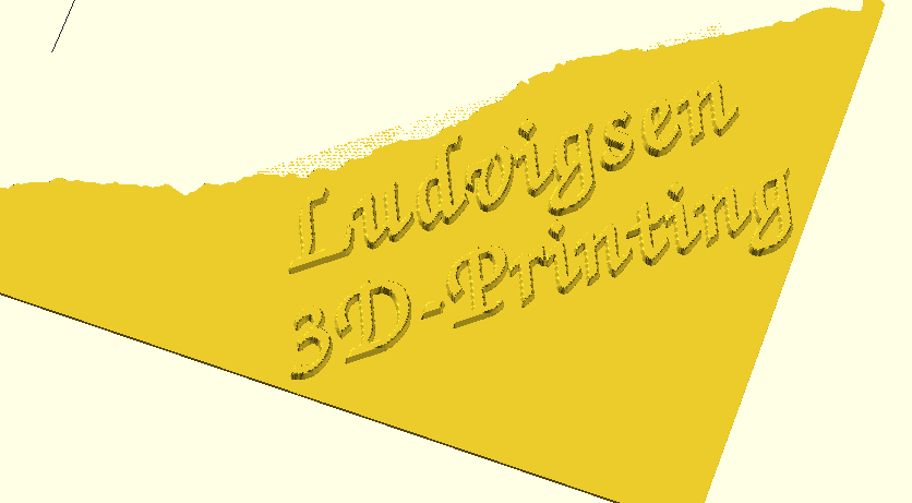
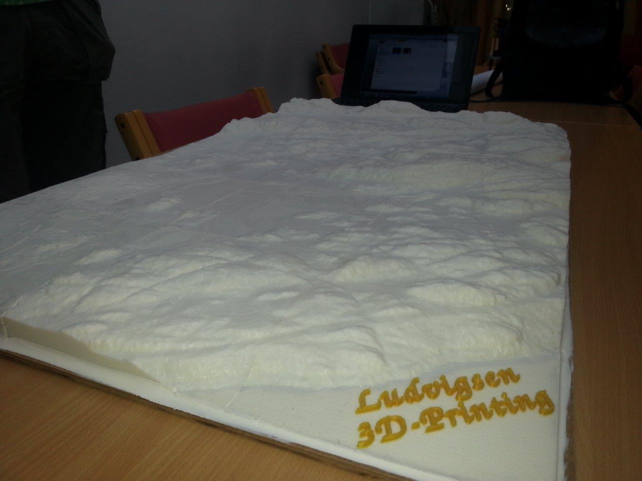
The improvised logo we put on top of the lake (Farris) in the model.
Thanks to text2surface
by polymaker for help with the text.
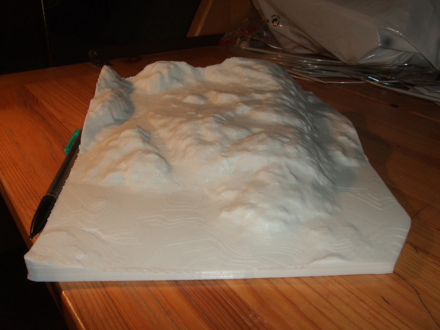
A view of the model from above.
A view of the model with the improvised logo in front.
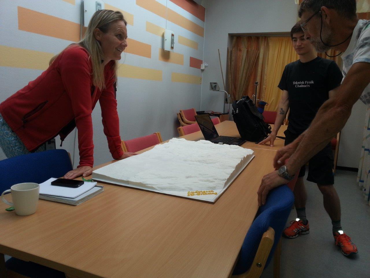
Delivering the model to the customer.
- tobben
Torbjørn Ludvigsen
I received a call recently, from the Geo-data department of the municipality.
They were developing some new housing in Martineåsen, and wondered if I could
print it for them, scale 1:2000. It turned out my dad had tipped them about my
RepRapping. I printed them a test piece and dad talked me into promising them
fifteen pieces of landscape prints,
each of them maximizing the print area of Gomle
(19 x 19 cm). I thought the project was total madness right from the beginning.
This would be an order of magnitude bigger than my most complicated print
thus far, and it was to be done with the most unstable printer I've ever built,
having access to two old laptops as my only computing power.
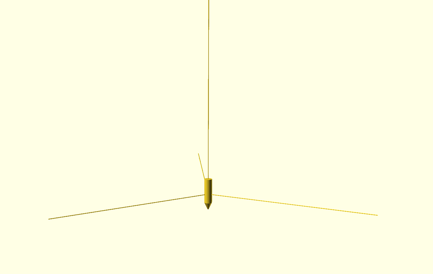
A Hanging RepRap
15-5-2014
Sketch showing the basic layout of the hanging RepRap.
I've dreamt of a RepRap that uses ceiling and walls its frame for some time now.
It would use lines and spools instead of smooth rods, belts and linear bearings.
This blog sort some of my thoughts around it.
The idea
The printer I dream of would be all in one hanging unit, interfacing with the
outside world only through filament (direct extrusion), hot end, power chord
and four lines. Microcontroller, stepper motors and extruder would all sit on the
hanging unit, so the room in which it operates wouldn't need to add any other
details than four anchor points.
Benefits
No time spent building frame, except four anchor points.
Large print volumes.
Would require no desktop when idle, if it could retract itself up close to the ceiling.
Cheap.
Few parts.
Difficulties
Make firmware compensate for the unusual geometry.
Avoiding rotations.
Making anchor points.
The unusual geometry isn't actually that tricky to compensate for. We have four
lines, so every point in the print volume will have a corresponding tuple of
four line lengths. Converting from Cartesian xyz-coordinates to these tuples
of four line lengths is just a matter of using Pythagoras' theorem.
Calculating the distance from anchor point 1 to the point (x',y')
with Pythagoras' theorem.
The issue of avoiding rotations is the one I fear the most. Maybe it is necessary
to hang the printer in 3 lines from the ceiling, and use 2 parallel lines to each
of the remaining anchor points, to make the printing unit stable enough. That
configuration is the one used by brandonheller's
SkyDelta.
The SkyDelta is by the way proof that a hot end can be given stable movement,
only by using lines.
Making anchor points is maybe the biggest no-selling argument for this type
of printer that I can see. While anchor points saves the desktop space, and
makes it possible for people in small apartments to have a dangling printer,
I suspect that many don't want to/can't screw that many holes in walls and
ceiling.
The first prototype of the hangprinter. Meant to only be able to print
in 2d. This is to be able to test if the geometry/firmware problem is as small as
I suspect while not having to worry about rotations.
Torbjørn Ludvigsen
I've dreamt of a RepRap that uses ceiling and walls its frame for some time now.
It would use lines and spools instead of smooth rods, belts and linear bearings.
This blog sort some of my thoughts around it.
Second Attempt at Printing the Grue
22-4-2014
Made a second attempt at printing the Grue figure from the (really cool)
Teslagrad game. My last attempt was documented
here.
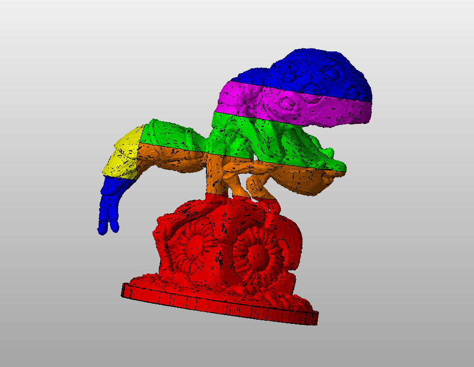
This time around, I decided to go for splitting the figure in several
planes parallel to the xy-plane and the yz-plane, and keep the auto-generated
support material setting in Slic3r.
To do the splitting, I used Netfabb Basic's really nice splitting interface. I prefer
simple, light and open software, so I tried splitting with OpenSCAD and Slic3r first,
but the file were simply too messy and I didn't manage to repair it. I have to say
Netfabb is pretty good at handling stls with intersections, holes, flipped normals and
that kind of stuff. Anyways, here's how the model was split:
The different pieces of the print in different colors.
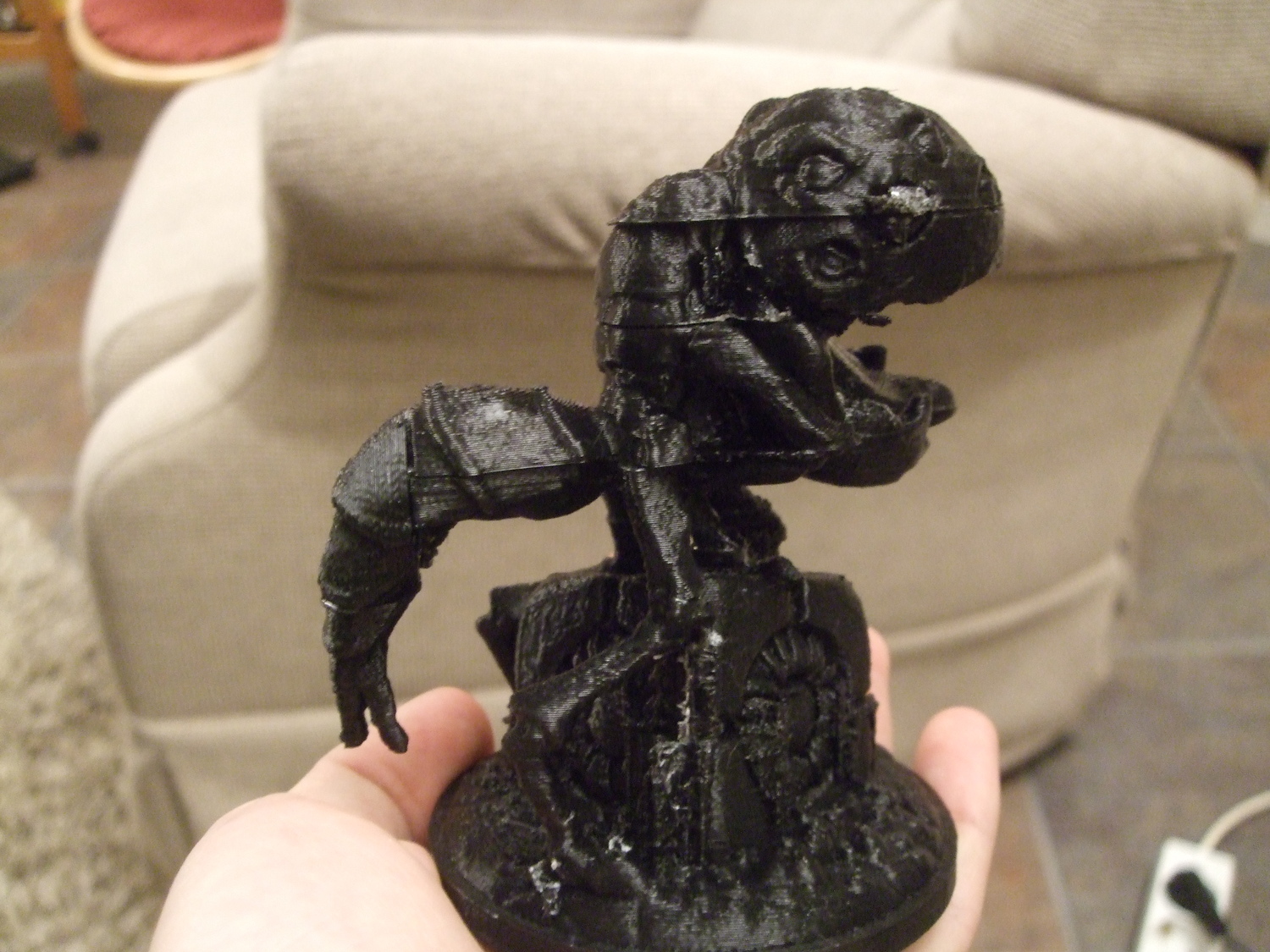
The print took ca 10 hours, glueing it together took ca 30 minutes and removing
support material never actually finished. Unfortunately, much of the support material was impossible to
remove, and some of the removed material took with it pieces of the actual figure.
The finished Grue, most of the support structures removed and pieces
glued together.
There are two aesthetic issues with it that really bothers me. First, the
clued contact surfaces did not fit each other perfectly. The clearly
visible lines you see in the picture was as good as it could get. I suspect this
mismatch to be due to a slack in the y-belt. The printer I used was
the Mendel
I built for my Mum and Dad last summer, and it hasn't
really received the love it deserves. The second issue is all the dots of
support structure that has tainted the figure like warts.
PLA support structures for PLA figures really sucks. I hope this is the last
time I try that.
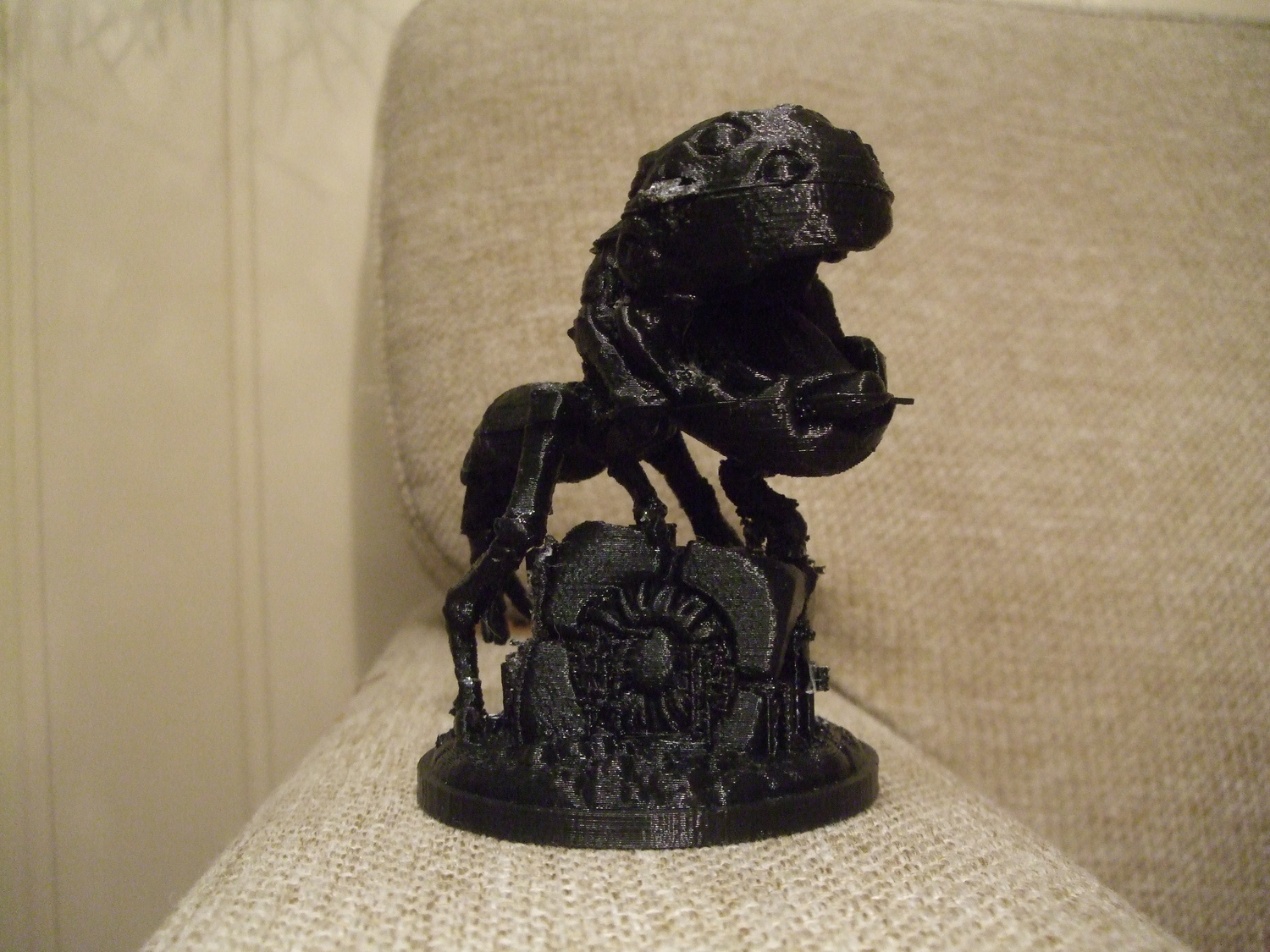
The Grue lives in the Dark. It eats small children.
It can smell them through any wall. It eats them in a single bite. The child is dead
within a fraction of a second. Fortunately the kid has infinitely many lives. Hope you
remembered to save game.
I will probably try to print this again, since I can't stop bothering about those
little issues...
- tobben
Torbjørn Ludvigsen
Made a second attempt at printing the Grue figure from the (really cool)
Teslagrad game. My last attempt was documented
here.
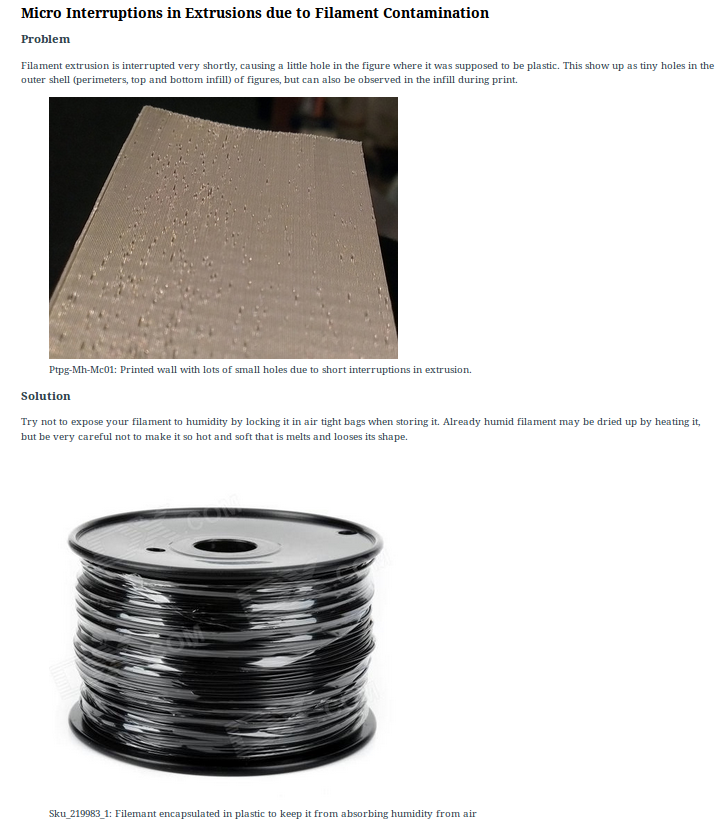
What Print Issue Solution Filter Is and What It Does
19-4-2014
Hi there, Internet! The past week, I've gotten some feedback that people (even
really technically talented ones) don't understand what
the web app
is and what
it does, so I thought I might try to give an explanation.
I'm considering renaming it to something like Mini Article Structuring and Searching App
or something, because there's nothing in the Lisp code that's specific to RepRap.
The users decide what kind of knowledge is structured with it, but anyway let's use
RepRap knowledge as our driving example.
Defining the Mini Article
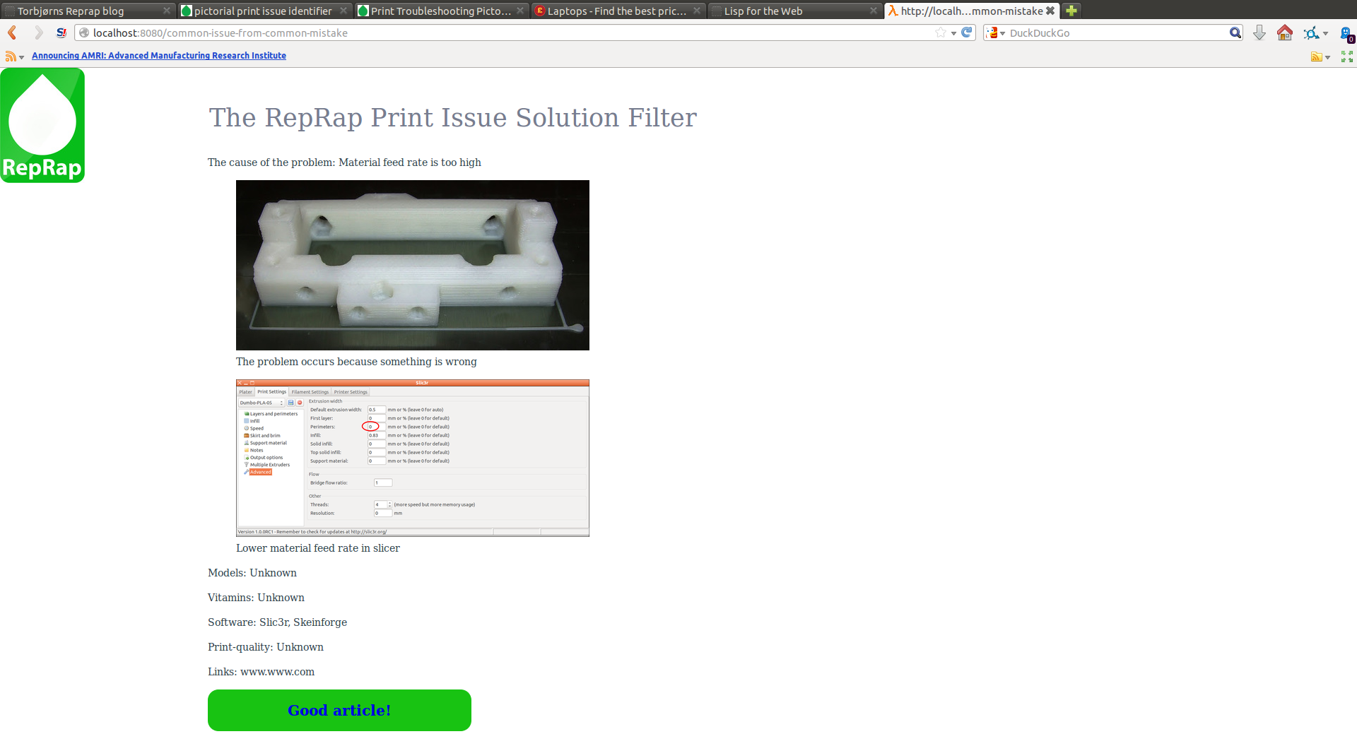
The first thing PISF does to structure knowledge, is defining a short but strict template,
called a Mini Article, that has seven things:
A title
A written description of a problem
A picture explaining the problem
A caption to that picture
A written description of a solution to the problem
A picture describing the solution further
A caption to that picture
A short but complete mini article.
By reading a lot of RepRap blogs, I have observed that many of us perform small
pieces of pretty well structured research. Often the aim of our little experiments
is optimizing a small detail of our 3d printing setup. My thought was that the
Mini Article template could serve a similar role as report templates does in the
academical world.
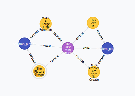
Sorting Mini Articles
PISF stores these Mini Articles as seven nodes in a graph database. The layout
looks like:
The layout of the Mini Article in the graph database.
The purple node carries the Mini Article itself,
the yellow nodes represent paragraphs and the blue ones represent pictures/figures.
The paragraph nodes and the picture nodes may have relations that point into
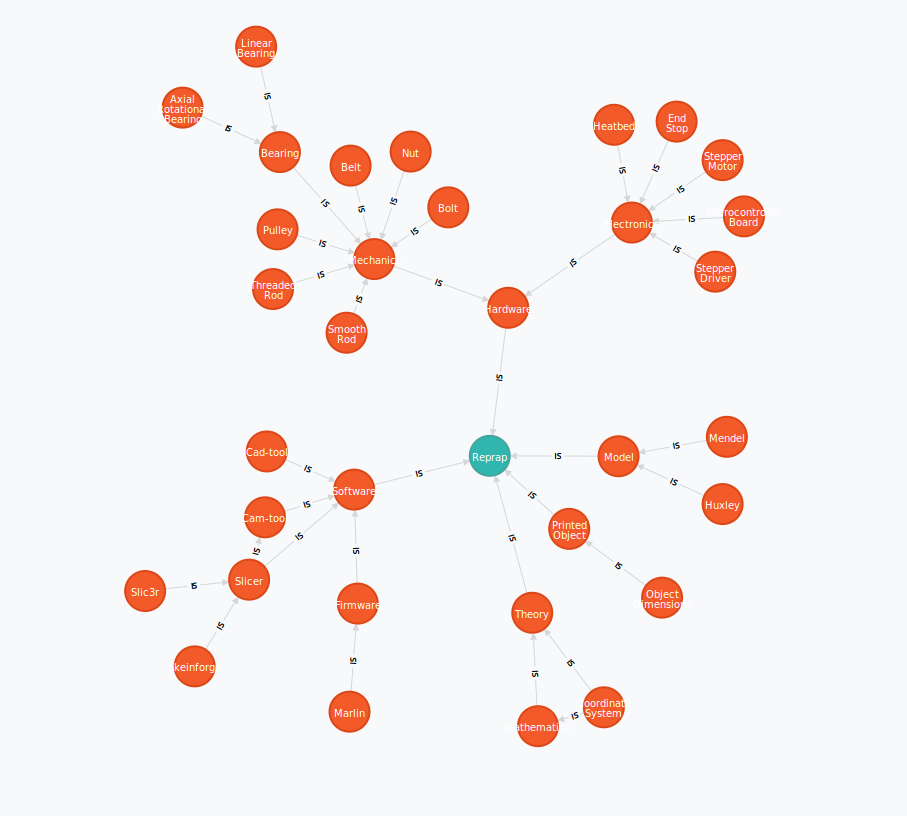
another set of nodes, called the "Category Bush". It looks like:
The layout of the category bush, that works like a tag hierarchy. It's not
a tree because it may contain loops. The only thing not allowed is IS-relations
going both ways between two nodes.
Searching Mini Articles
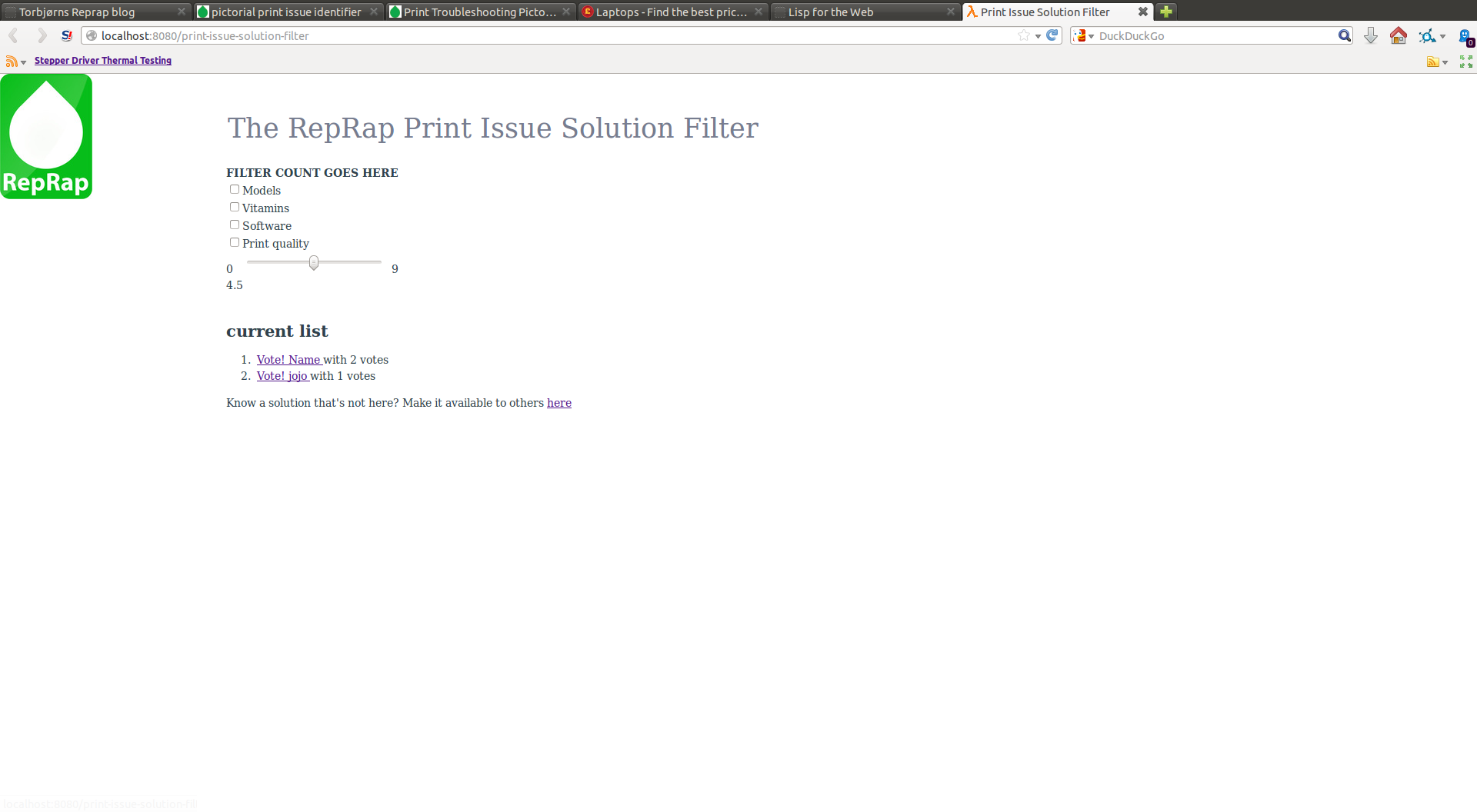
Arriving on the PISF homepage,
the user is presented with a set of checkboxes.
The names of these are loaded directly out of the Category Bush by starting in the
Reprap node (the green one in the figure above) and traversing one step outwards
via IS-relations. When the user checks a box and presses filter,
checkbox-structure is rebuilt, with the node corresponding to the checked boxes
treated like the Reprap node was before, in its own hierarchy of sub-checkboxes.
It looks like this:
The hierarchical checkbox structure is drawn based on user input and
the category bush. This user is interested in Mini Articles about the model Huxley.
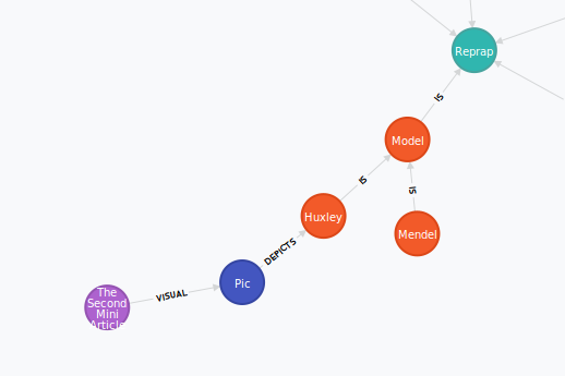
Back in the graph database, PISF will find the paths of the following pattern:
Any Mini articles with the following pattern of relations will be found
by PISF when searching for Model-related or Huxley-related articles. If the Huxley node had any
subcategory nodes, the Mini Articles with relations to them would also be counted
as relevant, so a Mini Article with relations more specific categories will
more often be found relevant by PISF.
The user that just pressed filter will be presented with an updated list
of Mini Articles. They are first sorted by relevance and then by number of votes. Relevance is found by
counting the number of paths from the chosen categories to the respective Mini Article.
That count is including the paths that go via sub-categories, but excluding the paths containing a
loop in the category bush. It looks like this:
List of found Mini Articles about Hardware found by PISF and presented to user.
That's it for today. I'll come back to this pisf-thing when I've tried to actually use it ;)
- tobben
Torbjørn Ludvigsen
Hi there, Internet! The past week, I've gotten some feedback that people (even
really technically talented ones) don't understand what
the web app
is and what
it does, so I thought I might try to give an explanation.
We're online! Sort of...
14-4-2014
I just got my little web app, PISF, up and running on a server. Go check it out
here!
As you will see, it only has three articles as for now. Making it available
to everyone was the last point on my prove-the-concept list. From here on I will
seek input, inspiration, ideas from you guys. If people like it, maybe we can develop
it further together.
Web programming with common lisp has mostly been pure amusement. The few daunting moments
I've had has mostly been caused by bugs in
Slimv
(once it actually refused to compile my code because of a parenthesis inside a comment!
I feel like a bad person for not bug reporting that properly. Sorry), and other
external programs.
If you enjoy reading lisp source-code, here are a list of my favourite parts
(see the github repo for the code):
The macro bind-cypher-returns-and-loop found around line 50 in
pisf-backend/pisf-backend.lisp.
The package-wise logging system defined in the three logging.lisp files.
(Thanks to a git-repo I stumbled upon and stole this idea from. I honestly can't find it again.)
The macro name-conventionize found around line 30 in
pisf-backend/pisf-backend.lisp
Discovering that a triangular pattern in a graph-database lets me
reuse nodes while avoiding confusion. Look at pictures in pisf-backend/screenshots
to see how the mini articles are laid out in the graph database.
The Cypher (database) queries needed to maintain this structure turned
out to be monsters, but that's another story.
Discovering that I did not have to worry about loops in the tag/category
hierarchy, because Neo4j will stop matching if it finds the same relationship twice
in a single path during a single search.
Discovering that I could sort based on relevance and based on votes, just by
adding ORDER BY relevance DESC, votes DESC in line 187 in
pisf.lisp.
Discovering that I could build a Cypher query in a loop quite easily.
This is used around line 510 in pisf.lisp, merely as a way of getting
around having to pass node-id's from one page to another, but amusing nonetheless.
A lot of Edi Weitz' work, that I've taken huge advantage of,
is beautiful. cl-ppcre:do-matches made the job of writing
escape-except-links (line 370 in pisf.lisp) so easy,
I felt like I was cheating.
Obviously there are plenty of flaws in the code too, but I don't want to start
listing those in this blog post. Those are the worries of tomorrow.
Getting Hunchentoot to actually serve outside my local network was a lot more
tedious than I'd expected. In the end, I found a wonderful
tutorial
that led me to webfaction's hosting service.
My experience with them so far has been as awesome as they promise in their ads.
Through ssh'ing my hired server, I've been able to
Compile Clisp from source with already installed make
Compile SBCL from source with newly compiled Clisp
Download and install Quicklisp
Download Oracle JDK 8 and Neo4j and run them
In addition, opening a port for Hunchentoot to serve through was a breeze using
the webfaction web interface, after a quick look at the documentation.
- tobben
Torbjørn Ludvigsen
I just got my little web app, PISF, up and running on a server. Go check it out
here!
As you will see, it only has three articles as for now. Making it available
to everyone was the last point on my prove-the-concept list. From here on I will
seek input, inspiration, ideas from you guys. If people like it, maybe we can develop
it further together.
Presenting the Print Issue Solution Filter. Again
4-4-2014
I've been working a this idea of a web app that filters small articles with RepRap know-how for a few weeks now.
The idea is to let people find specialized information fast, without typing.
A screenshot from the Print Issue Solution Filter frontpage.
Check the boxes with things you think are relevant to your problem and hit filter.
Take a look at this youtube clip.
to see it in action. It also have got a github repo.
Hope you like it. I'll write more about it later.
- tobben
Torbjørn Ludvigsen
I've been working a this idea of a web app that filters small articles with RepRap know-how for a few weeks now.
The idea is to let people find specialized information fast, without typing.
Small soldering with cheap equipment
29-3-2014
I recently had the choice between doing a kamikaze soldering or buying another new
Melzi board, after one of the small people in the family happened to rip the
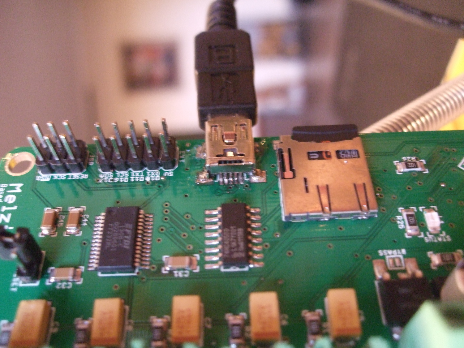
USB connector loose. Of course I chose the kamikaze soldering. I thought it
should be possible because the data transferring connectors had all broke in the
soldered points, so only solder was left on the PCB and all the data transferring
legs were intact. I only had to apply heat and pressure. The preparation was
in three steps:
Make the soldering irons tip completely flat with a file
Look really closely at the points to be soldered
Do it several times with a cold soldering iron to rehearse
I heated all the connectors simultaneously with the flat tip, for maybe one half
second, and it was done. Three of the four non-transferring legs (the corners)
had taken all the
solder with them when they broke, so I used two component epoxy glue to attach
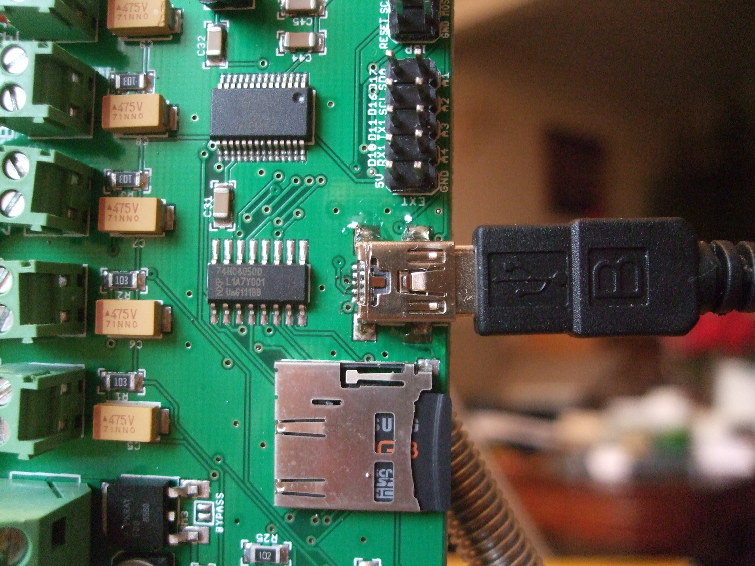
them firmly to the PCB. The result looked like this
A view of the repaired USB port of my Melzi board from the front.
A view of the repaired USB port of my Melzi board from the top.
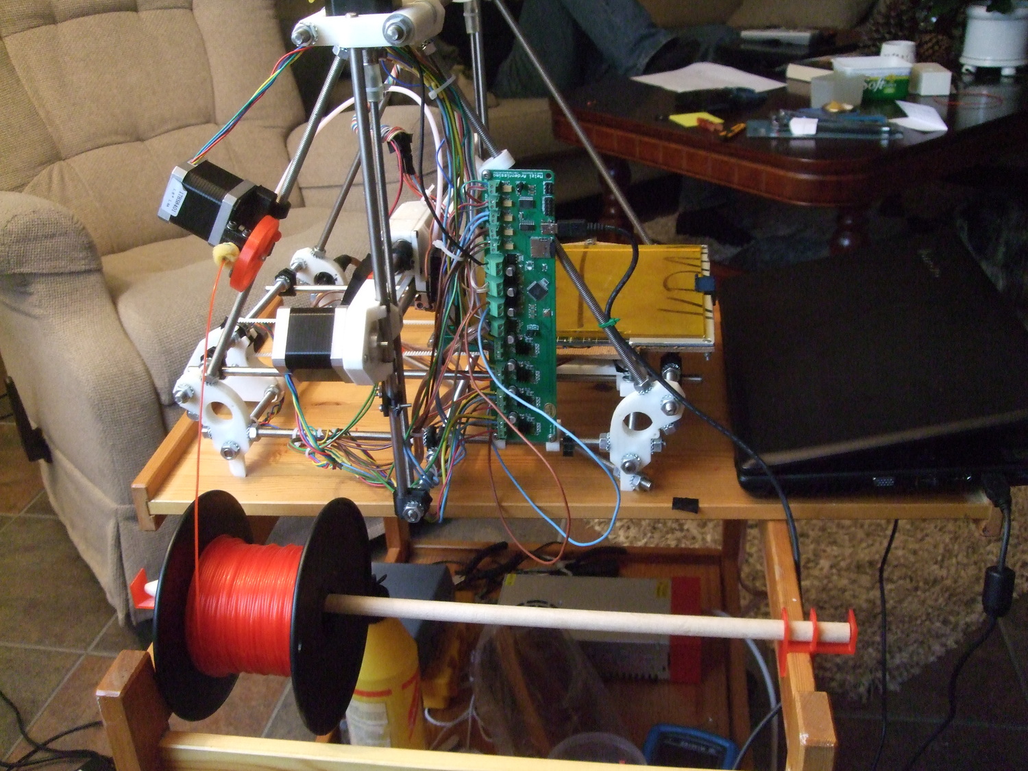
To save myself from having to do this too often, I now always zip tie my USB cables:
My USB cable zip tied to my Mendel.
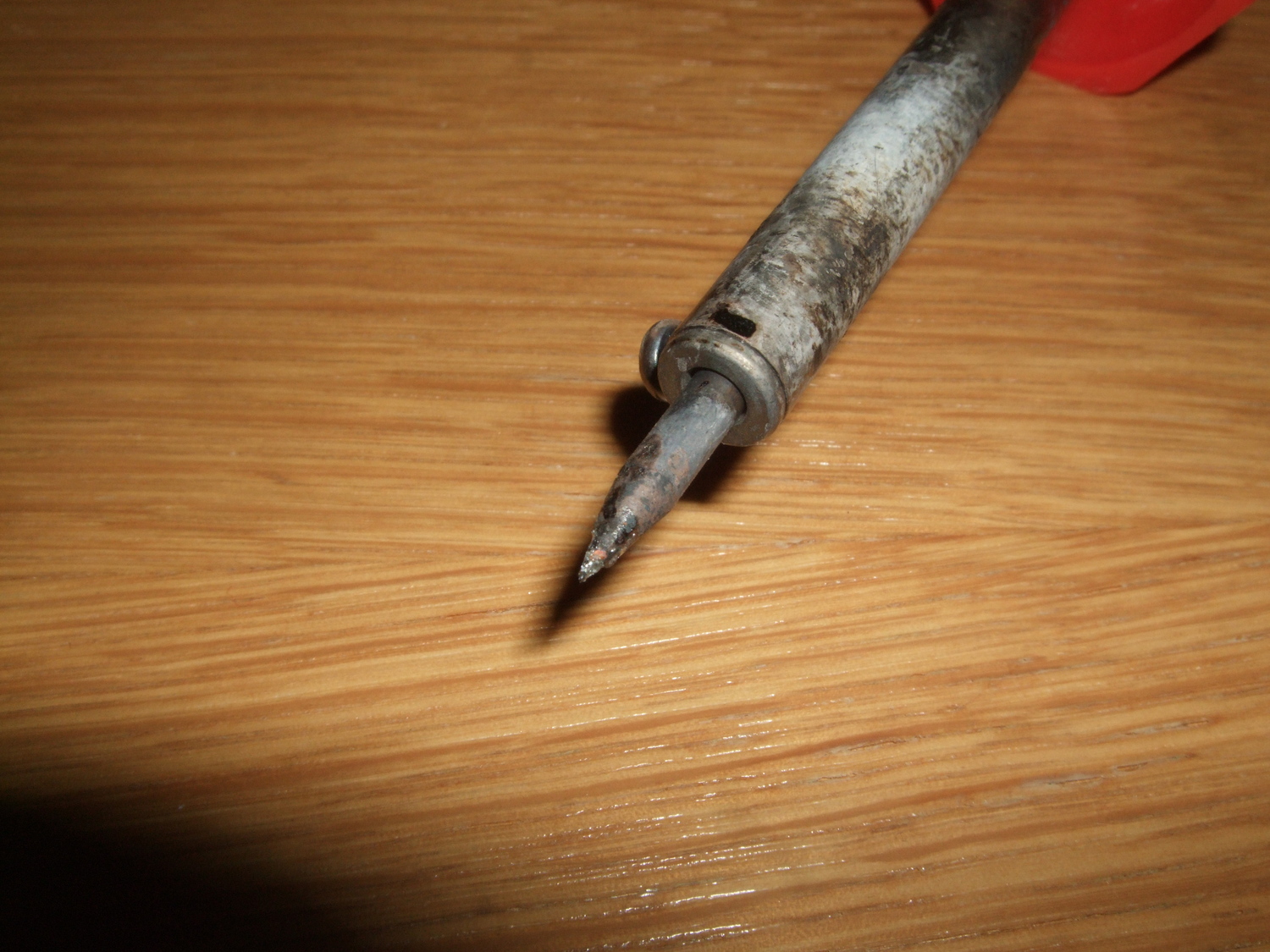
When building this same Mendel this summer, I had an even worse soldering problem.
Merlin mystically reported the z-home switch to always be open.
Investigations with a multimeter and with the help of the
datasheet
showed that the problem was a bad solder on
one of the processors legs! Luckily, this was one of the corner legs, so it
was one of the most accessible ones. My friend sluggo
taught me to file the soldering iron to a sharp point, like this
Soldering iron with sharp tip.
To avoid having to bend the processor leg, I wetted the tip with a minimal amount
of solder that I scraped onto the processor leg, not waiting for the solder
on the PCB to actually melt. This was the result
An attempt to photo the soldered leg of the ATmega1284P.
Looking closely at the large version (click the picture),
you can see that the reflections from
the solder on the bottom leftmost leg is a little distorted.
It worked perfectly ever after. In general my open hardware stuff
break more often than my other electronic hardware, but when it does it's more
often possible to repair because datasheets, code, explanations etcetera are
available. Occasionally I even learn something, and that has value too =)
- tobben
Torbjørn Ludvigsen
I recently had the choice between doing a kamikaze soldering or buying another new
Melzi board, after one of the small people in the family happened to rip the
USB connector loose. Of course I chose the kamikaze soldering. I thought it
should be possible because the data transferring connectors had all broke in the
soldered points, so only solder was left on the PCB and all the data transferring
legs were intact. I only had to apply heat and pressure. The preparation was
in three steps:
Making a Ring with a Rope
20-3-2014
My girlfriend and I are getting married this summer, and we thought it would be
nice to have the ring custom made, so I made a little sketch of our idea in OpenSCAD.
The sea is important to us, so we wanted to
symbolize that with a rope that runs in a track in the middle of an otherwise
plain wedding ring.
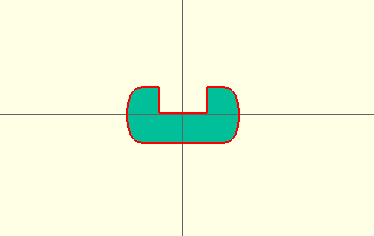
The plain ring with the track was really easy to get into OpenSCAD, because
of the rotate_extrude function.
The 2d outline of the plain ring with a track, that got rotated
into a ring by rotate_extrude. Thanks to jokern for suggestions
on how to model this.
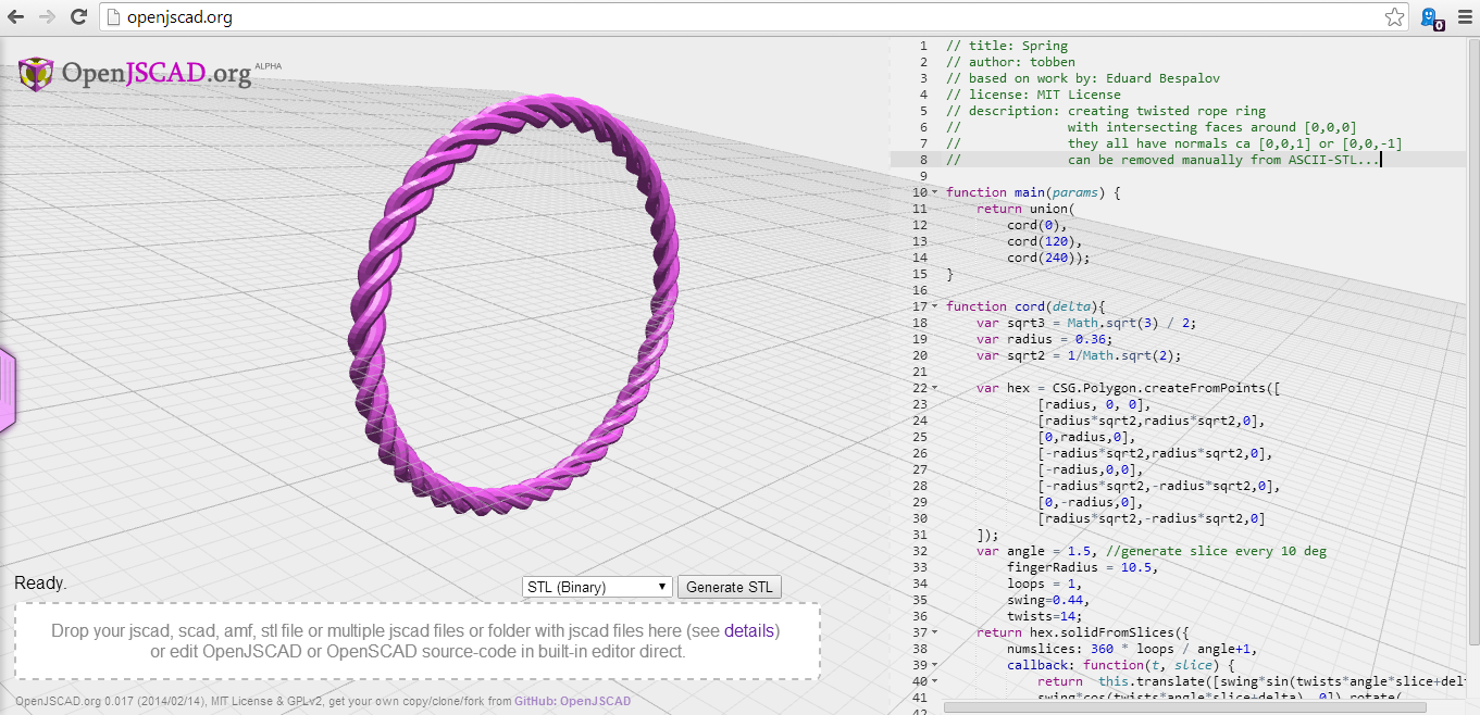
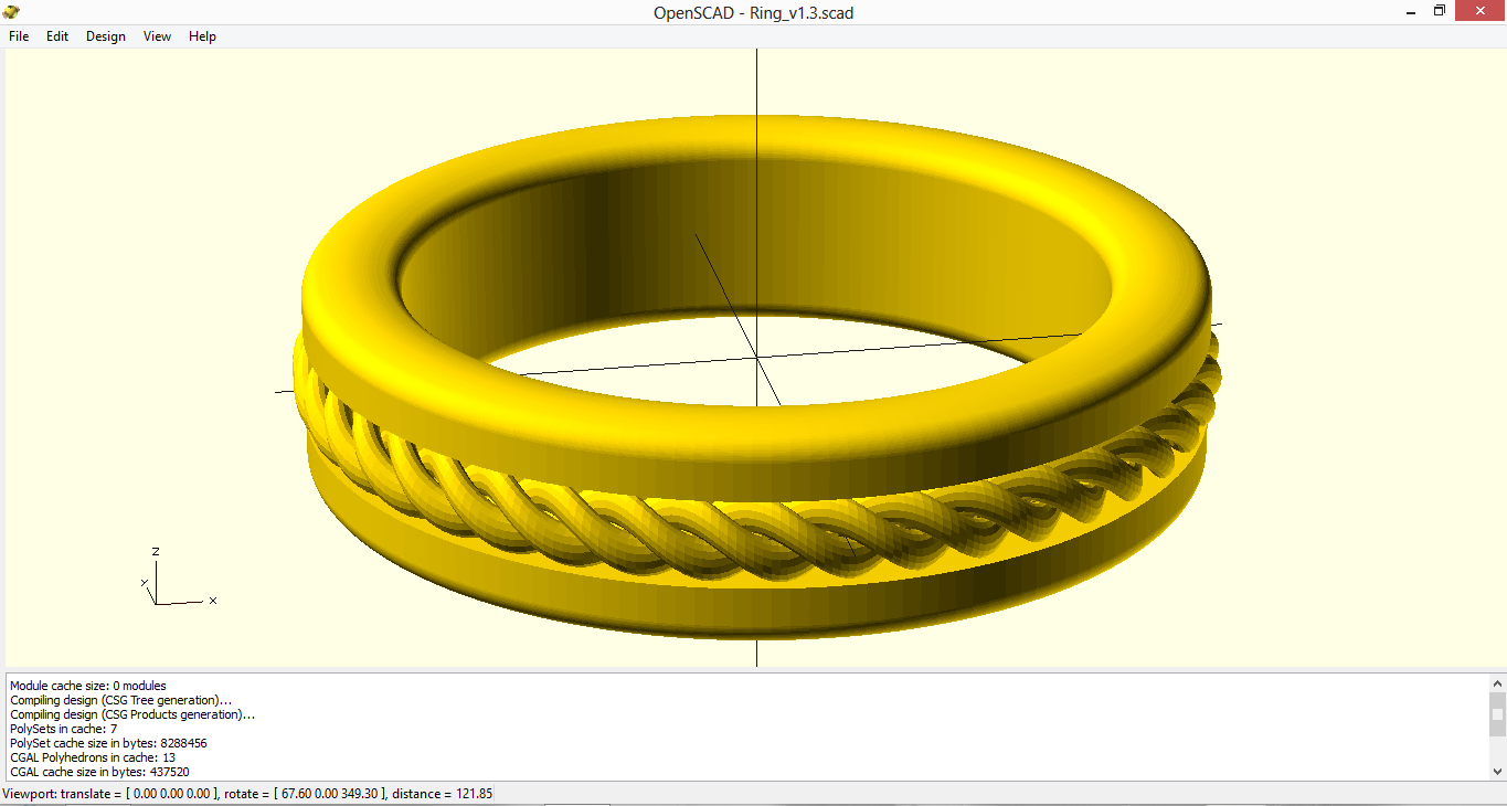
Cadding the rope was a bit trickier, because rotate_extrude
doesn't take any twist-parameter or anything like that. This turned out to be
a frustrating limitation, so I decided to try out
OpenJSCAD instead. To my delight, I found
that it had a method called solidFromSlices that seemed to
suit my needs.
A rope-ring cadded with OpenJSCAD and the method
solidFromSlices.
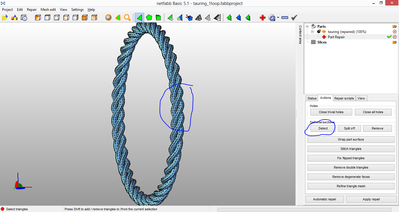
Unfortunately, solidFromSlices doesn't automatically detect that
it has created a loop (OpenJSCAD maybe has other functions for that, I didn't
get the complete overview), so the generated stl gets its "start-wall"
(start of the rotation) and "end wall" intersecting inside.
Detecting self intersections with Netfabb Basic.
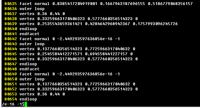
These self-intersecting surfaces made OpenSCAD refuse to import
the rope-ring from OpenJSCAD. Oh no! :-O Fortunately, the intersecting
surfaces had one special attribute that made them easily removable: They
were all lying flat in the xy-plane. I made an ASCII-version of the stl,
opened it with Gvim, and found several surfaces with normals exactly along
the z-axis
Looking inside the stl of the rope ring, I found several
facets with normal along the z-axis. Some of them had a
facet normal 0 0 1 and some of them deviated from that with
a number of order -16. The last line in the picture shows how to search for
these facets with Gvim.
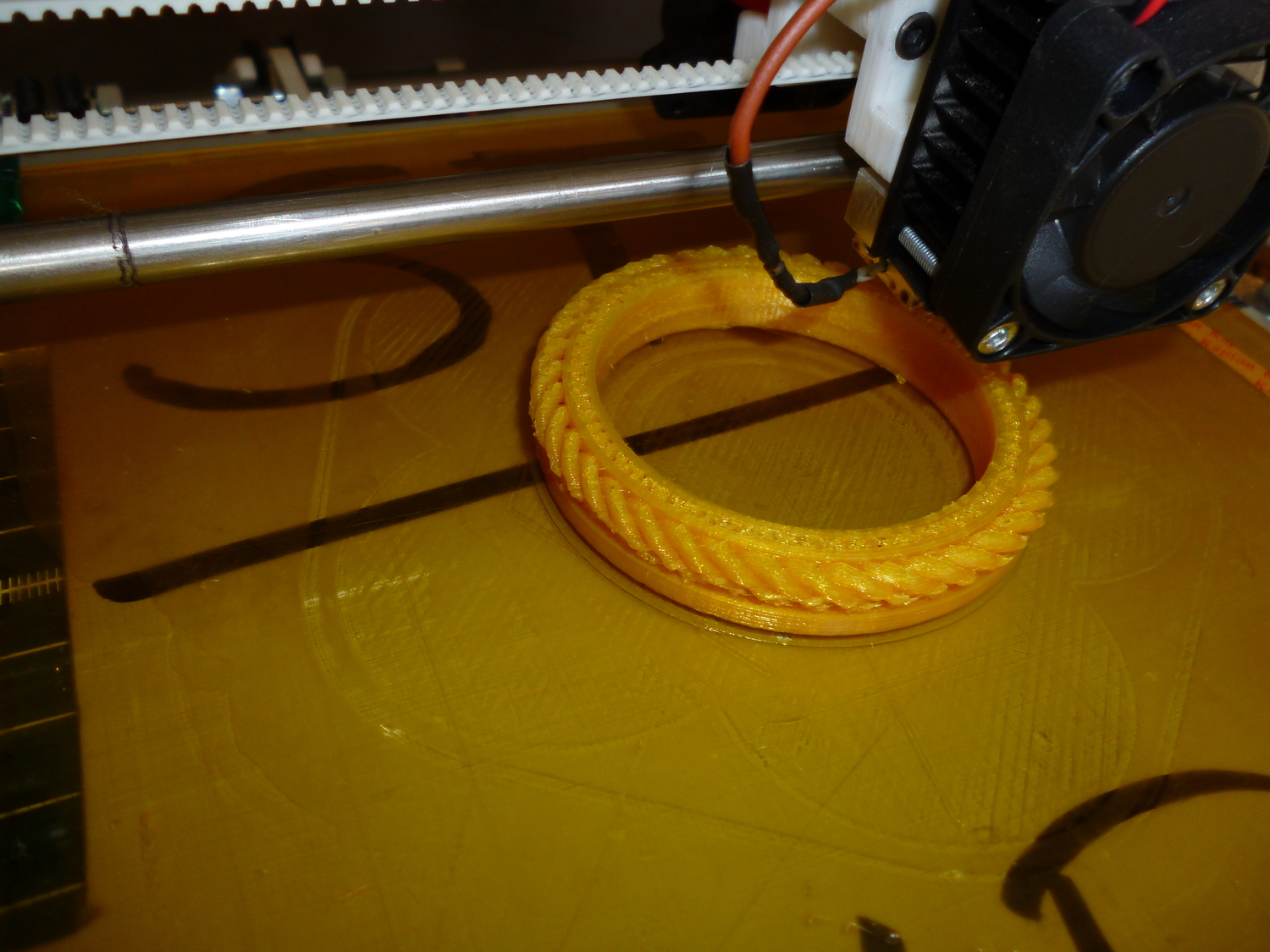
With all the intersecting facets removed, importing worked like a charm again.
A render of the first ring that got printed. Lot of details
will probably be changed before the wedding though.
The first printed version of the ring, scaled up 300%, during print.
The files I used for this project (included the OpenJSCAD code) can he found
here. Hope you guys enjoyed.
- tobben
Torbjørn Ludvigsen
My girlfriend and I are getting married this summer, and we thought it would be
nice to have the ring custom made, so I made a little sketch of our idea in OpenSCAD.
The sea is important to us, so we wanted to
symbolize that with a rope that runs in a track in the middle of an otherwise
plain wedding ring.
Making PLA prints stick reliably
14-3-2014
I recently tried out a trick I learned from
NumberSix's 3D printing blog
and Richrap's blog
about applying a layer of diluted PVA a based glue to the kapton tape heat bed, to make PLA stick
better. One part glue and nine parts water was the first I tried, and it did the
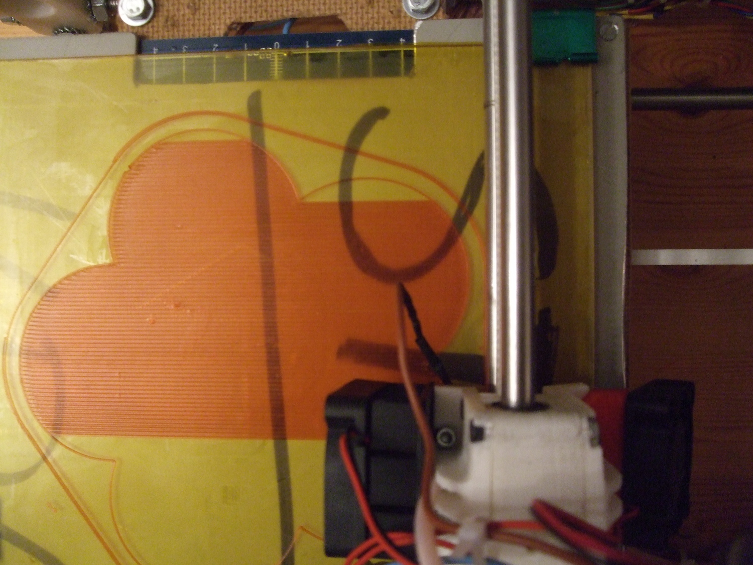
trick perfectly for me. After having had problems with getting my glossy orange PLA to stick
at all, big prints like this is now reliable like a walk in the forest
Big first layer of PLA on an PVA-prepped heat bed. Notice how
the kapton tape is slightly matte/white because of the thin glue layer. The
underside of the print gets a similar matte surface.
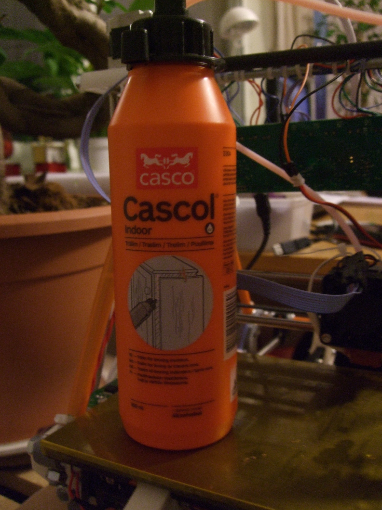
As well as keeping large prints from not warping, it lets even the tiniest
dots in a first layer stay in place. I tried two different glues that both worked fine.
Here is one of them:
A bottle of one of the PVC glues I tried to prepp my print surface.
This method may make your prints stick too hard to
your printbed. Start with small amounts. Also, first layer adhesion
depends on a lot of things, and is being eagerly discussed on the
reprap forums, so
not everything will work for everyone, but this is my go to solution for now =)
- tobben
Torbjørn Ludvigsen
I recently tried out a trick I learned from
NumberSix's 3D printing blog
and Richrap's blog
about applying a layer of diluted PVA a based glue to the kapton tape heat bed, to make PLA stick
better. One part glue and nine parts water was the first I tried, and it did the
trick perfectly for me. After having had problems with getting my glossy orange PLA to stick
at all, big prints like this is now reliable like a walk in the forest
A Very Short Introduction to Basic RepRap Workflow
6-3-2014
This is for you who somehow have gotten you a ready-to-use RepRap, but don't
have any previous experience with either RepRap, 3d-printing or CAD software.
We're going to print a calibration cube, and I'm just going to assume that
everything goes smooth. Billions of things that can go wrong, but I will avoid
mentioning too much about them.
The programs chosen are just the ones I use. They're not good, nor bad. They
just are what they are.
Start with downloading and installing OpenSCAD.
When installed and executed, it should present to you a window like this:
A screenshot from OpenSCAD taken directly after it was started.
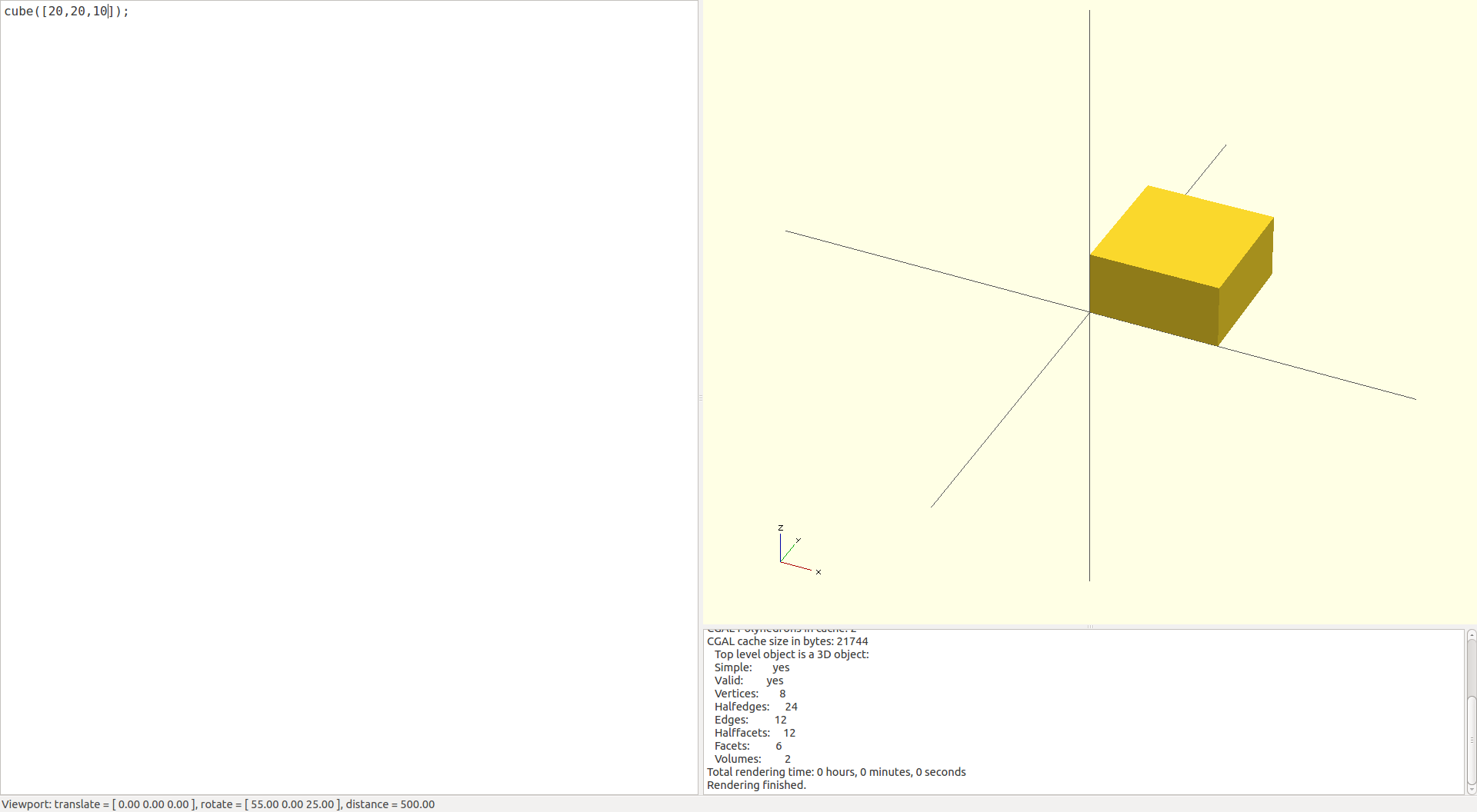
We want our calibration cube to be 20 mm wide, 20 mm deep and 10 mm high, so we
enter cube([20,20,10]); into the text editor in OpenSCAD, and
compile and render it. The "Compile and Render" is done either by pressing F6,
or by finding Design > Compile and Render (CGAL) in the menus.
Your OpenSCAD should now look like this:
A screenshot from OpenSCAD with a compiled and rendered calibration cube.
We now want
to export our model to a format that the next program in our tool chain can use.
We choose the most widely used format, which is called .stl. You export it from
OpenSCAD by finding Design > Export as STL... in the menus:
The menu in OpenSCAD that lets you export to the stl-format.
The modelling is now finished, and we start to prepare the model for the printer.
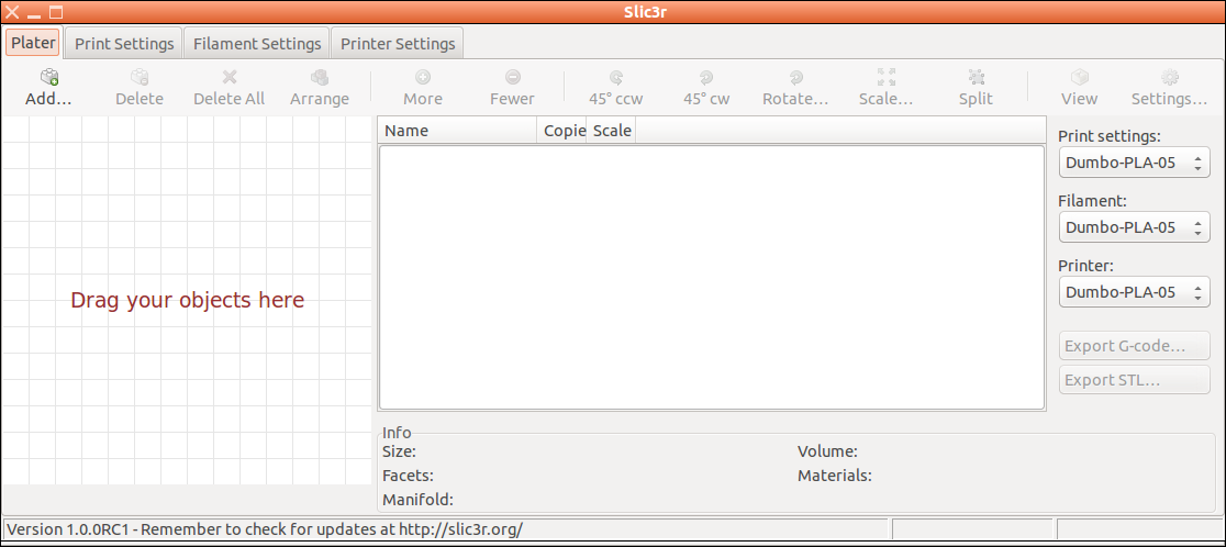
Download and install Slic3r.
When installed and executed, it should present to you a window like this:
A screenshot from Slic3r taken directly after it was started.
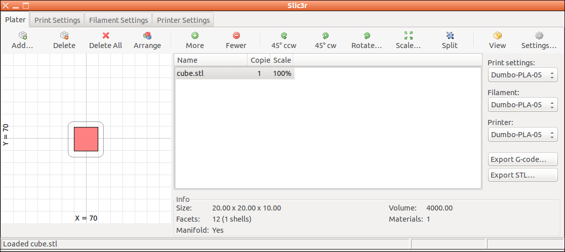
To import the calibration cube, press Add... button.
When the cube is imported, it looks like this:
A screenshot from Slic3r taken after a cube was imported.
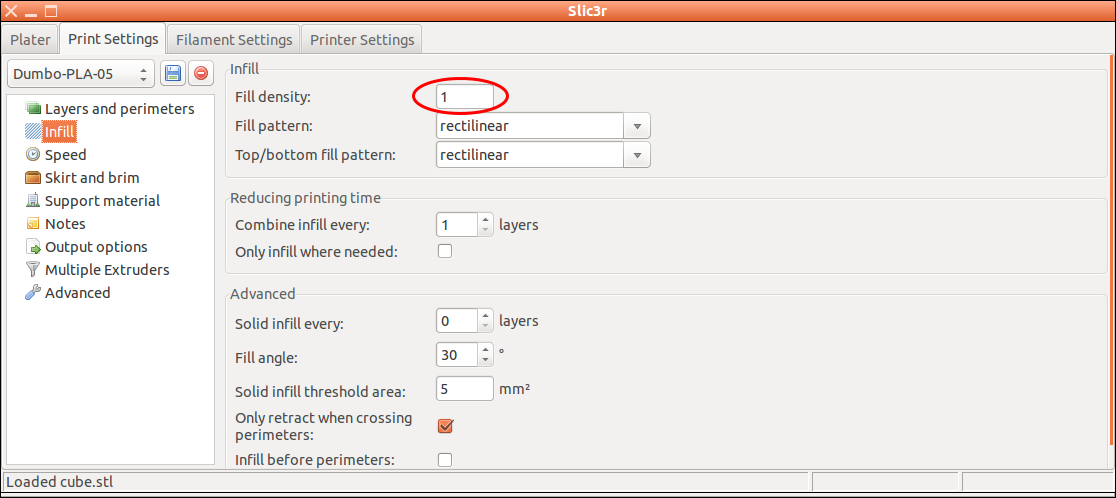
Slic3r is a program with many options. We're just going to look at ca five of them.
First, we want to assure that the cube is printed as a solid cube. Click
the tab called Print Settings and in the menu on the left click
Infill. We want to set the Fill density to 1:
The first option we want to change in Slic3r is the fill density.
To prepare printing a solid figure, set it to 1.
Click "Save" (the little blue icon) and note the name of your Printer Settings config
(To the left of the blue icon). The next
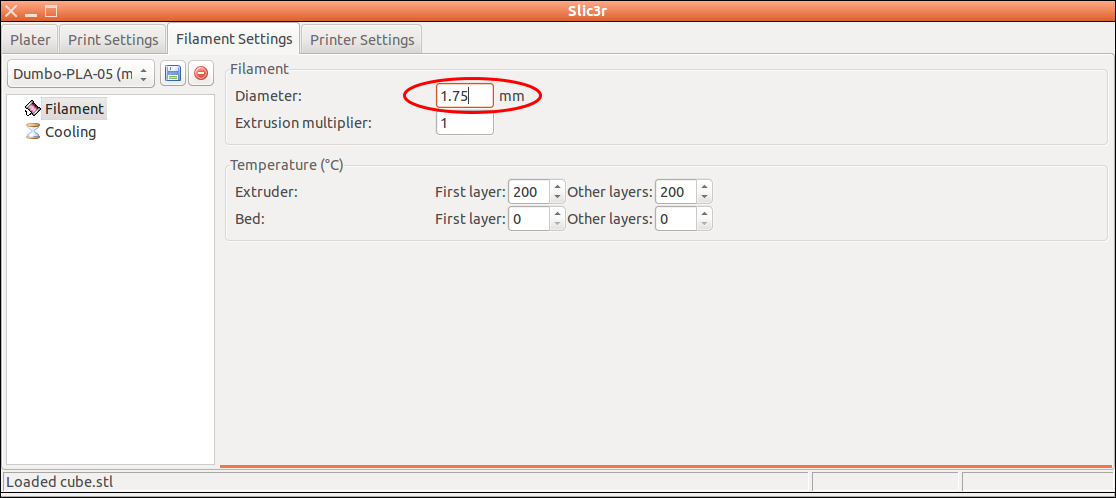
option we're going to change is in the Filament Settings tab.
The default value for Diameter is 3. Measure the diameter of your
filament with a caliper, and put the measured value into the Diameter field.
Telling Slic3r that the filament I'm going to print with has a 1.75 mm diameter.
Again, click "Save" and note the name of your Filament Settings config. Note that
the default extruder temperature of 200 degrees Celsius works well if your
filament is made out of PLA. If you're not sure what kind of filament you have,
check it up first.
Also, if you don't have a heatbed, put
the bed temperature of 0 degrees Celsius, like shown in the figure. If you have
a heatbed, and will be printing with PLA, anywhere between 40 and 60 degrees Celsius
is a good starting point for experimentation.
Next, we're going to look at Printer Settings. Measure the bed size of
your printer. Feed the measured values it into the Bed Size fields,
and put the values divided by 2 into the Print Center fields.
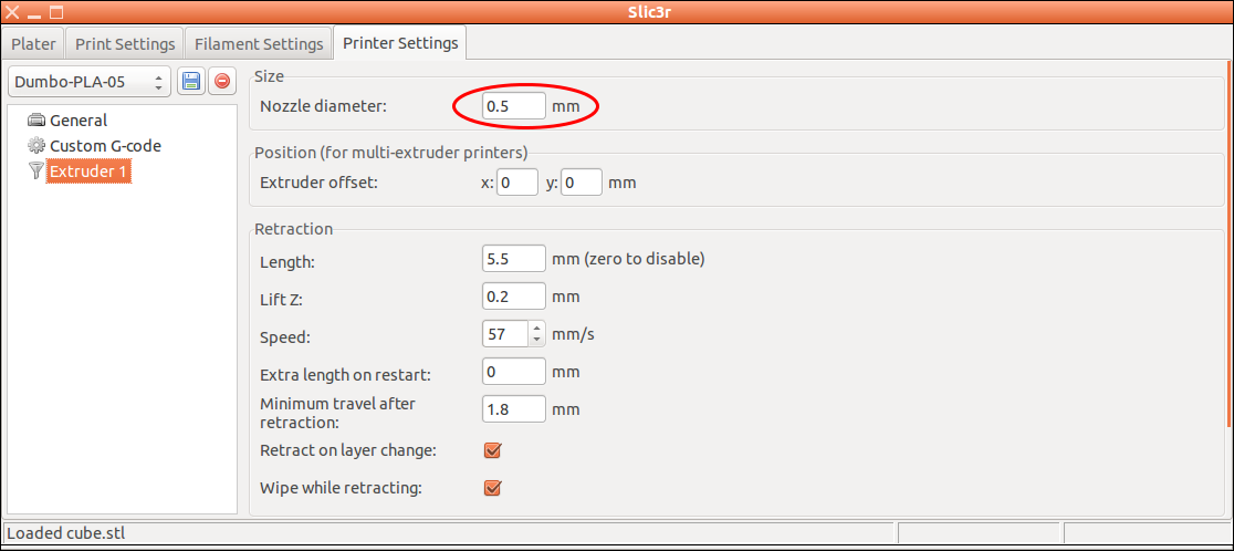
The last value to check/update is in Printer Settings, Extruder 1, Nozzle Diameter.
If you don't know your nozzle diameter, check it up and feed in the correct value.
Telling Slic3r that my RepRap's nozzle has a 0.5 mm diameter.
Save your printer settings and return to the Plater tab.
Assure that the names of the
Print Settings config, Filament config and Printer Config
are the same ones as the ones you saved to earlier.
Next, press the Export G-code... button and save the .gcode file
somewhere you will find it later on. You have now created the actual data that
will be sent to your RepRap! The next step is learning how to send it.
Download and install Printrun/Pronterface.
If you're on Windows, maybe this link
can be of help.
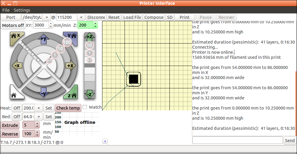
When installed and executed, it should present to you a window similar to this:
The interface given to you by the Pronterface program.
Click the connect button. Hopefully the printer will respond
with "Printer is now online." or something similar. On Windows machines, it will
probably not. At least on W7 and older, you will need to install drivers
to communicate with the printer.
When the printer is connected, we want to load our gcode. Press
Load file and select your file. Pronterface should now look
something like this:
Pronterface with calibration cube loaded.
If you've come all the way here, you're now ready to press print.
Your printer should respond by starting to heat up its hot end and start to
print the first layer within a few minutes. The print will probably have an awful
lot of problems, depending on how "ready-to-use" your printer really was.
I would estimate a less than 1 % chance that the info in this post makes a total
newbie able to print him/her-self a cube. You will probably need some more
specialized info to get all the details right, but I hope this post has enabled you to ask the right
questions and/or trump your way through some of the loops without noticing
the potential pitfalls.
Torbjørn Ludvigsen
This is for you who somehow have gotten you a ready-to-use RepRap, but don't
have any previous experience with either RepRap, 3d-printing or CAD software.
We're going to print a calibration cube, and I'm just going to assume that
everything goes smooth. Billions of things that can go wrong, but I will avoid
mentioning too much about them.
The programs chosen are just the ones I use. They're not good, nor bad. They
just are what they are.
Printing litophanes
28-2-2014
I read Peter Blacker's excellent
blog post
about making lithophanes with RepRap recently,
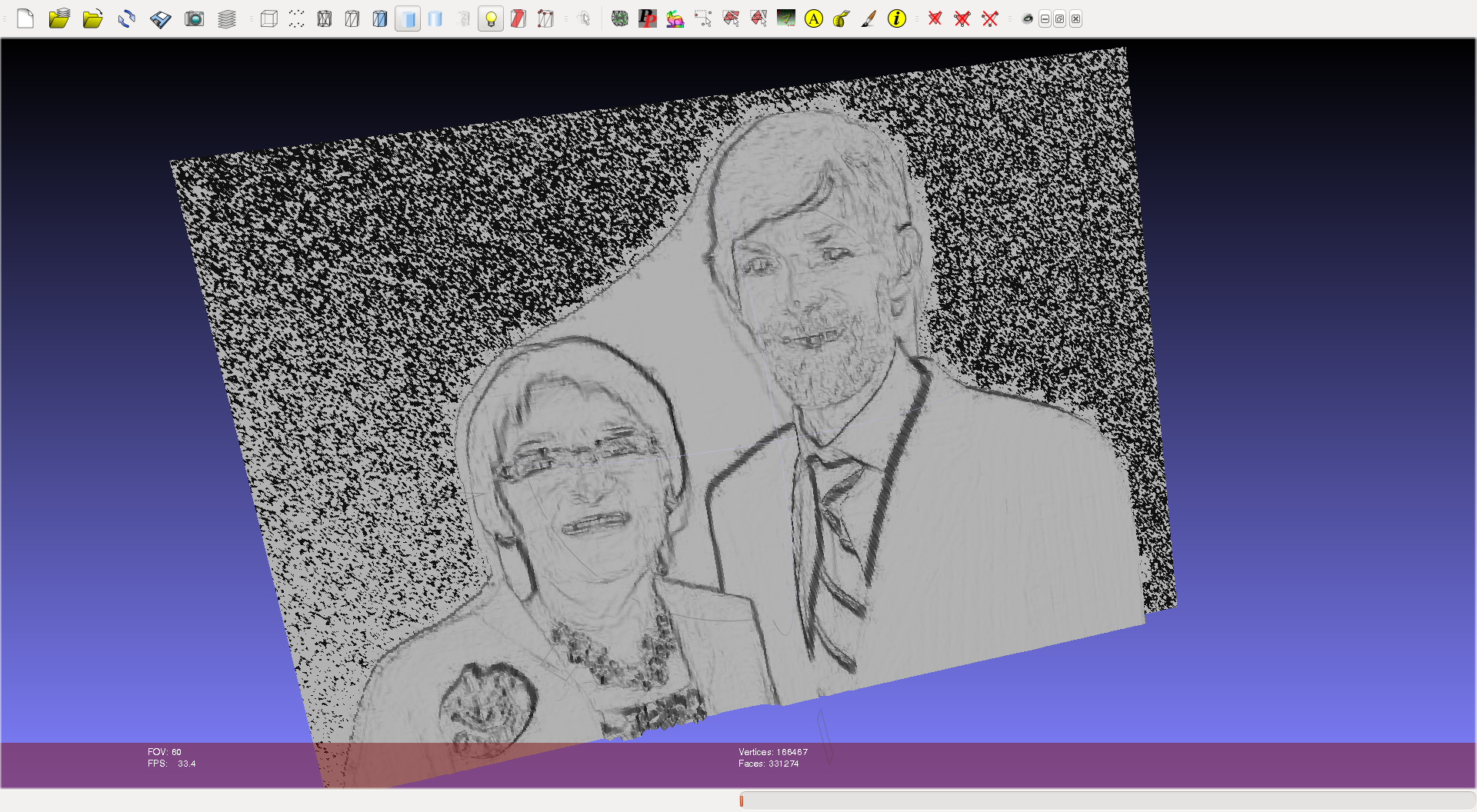
and was inspired to print a couple for my parents.
I first found a nice picture of my Mom, and scaled it down to 300x200 pixels
to make it easier to handle. I then used processing,
the
Model builder library
created by Marius Watz and a
sketch created
by Amanda Ghassaei. Her instructable
contains details about installing the library and using the script.
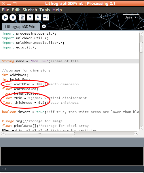
I put the file Mom.JPG in the same folder as the sketch and opened the sketch in
Processing. I followed Peter Blacker's advice and set zDim to 2, so I got
20 steps from white to black when printing at 0.1 mm layer height.
The settings I fiddled with in Amanda Ghassaei's sketch. widthDim is
interpreted as millimeters by Slic3r (he stl format don't carry information about units).
I also gave the tip about cropping pictures and putting thickness to 0
a go. The result was, as expected a very slim background, showing up as
"snow" in Meshlab, like on an old TV without a signal
An stl of my parents with a very thin background.
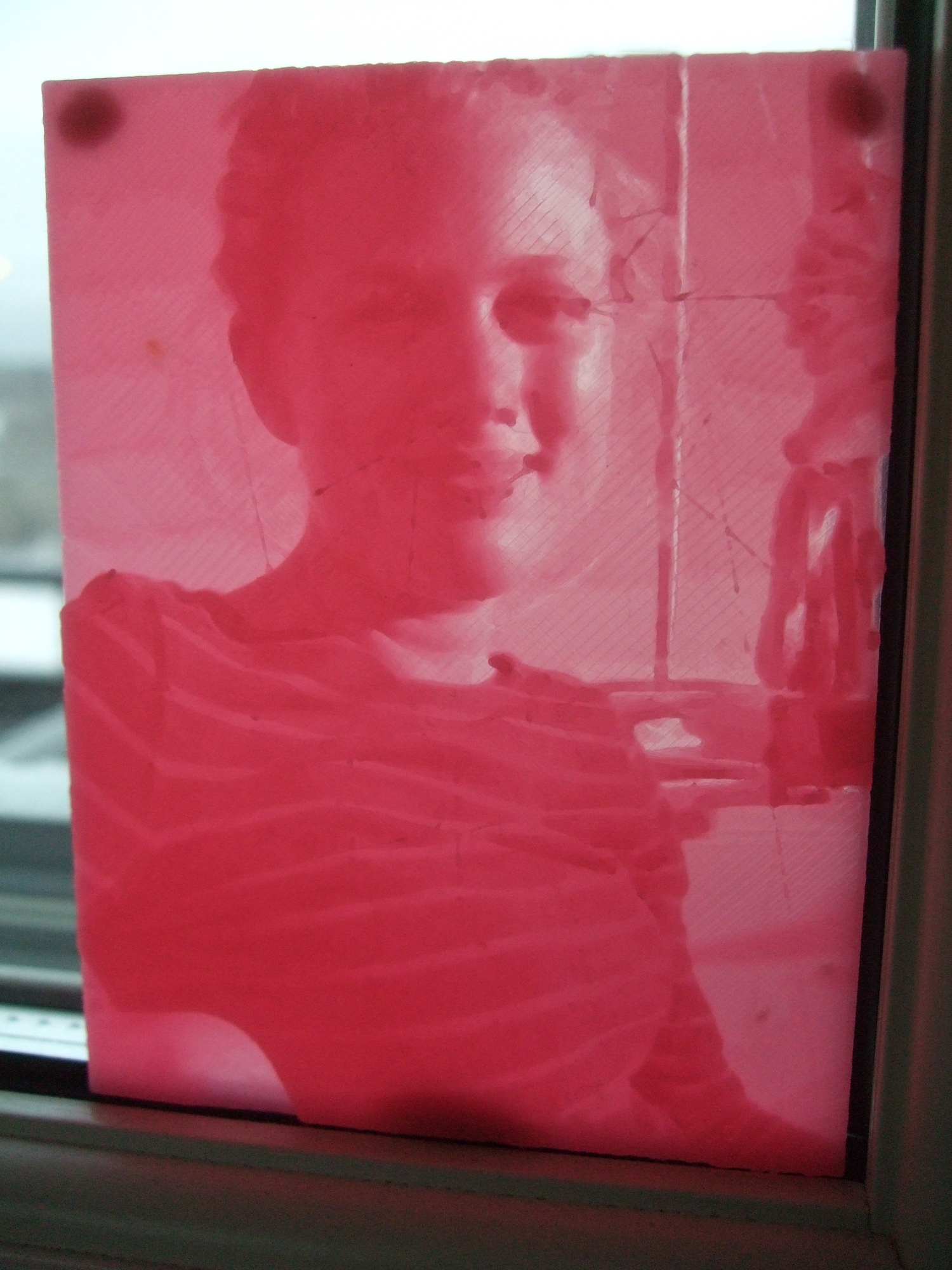
The results looked like this
Two pink litophanes of my parents. If you click it and look closely
you see that dad's shirt was so light it resulted in a hole near his tie.
The "noise" around Mum on the left picture is supposed to depict real snow.
Notice that the left litophane looks slightly more detailed than the right one?
The right one was actually made with more pixels per mm (500 pixels wide), and
had the same number of layers from white to black (20 x 0.1 mm).
I think the reason for the difference in detail if that when I sliced
the right one I was using "wipe on retraction", whereas when slicing the
left one, I did not. Z-lift was used on both.
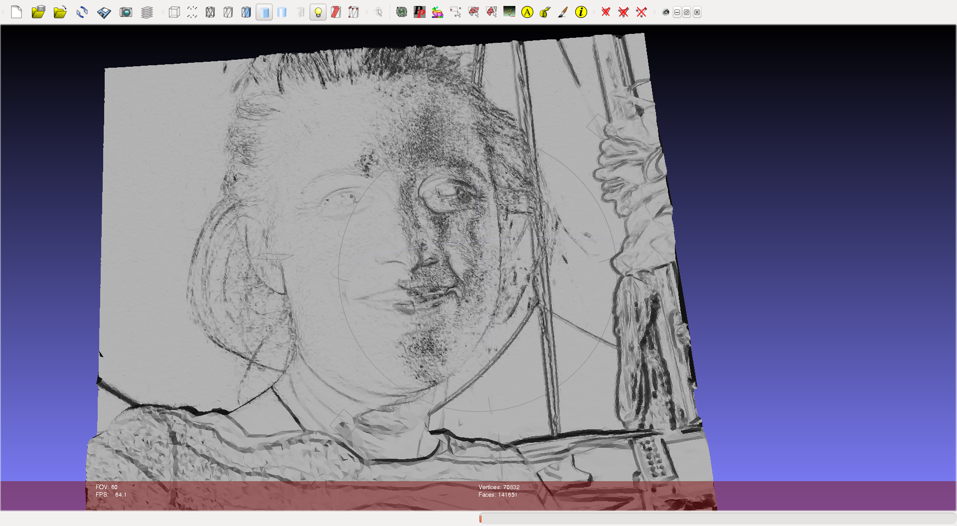
Before slicing litophanes of pictures with some more important parts (like human faces),
it can increase slicing speed to use the
reduce faces tip on the unimportant parts.
Mark the unimportant vertices before making the reduction.
A simplified stl of a face.
Notice how the "ropes" hanging down on the right has much less detail than the face.
This one came out pretty nice, but shows signs of drooling
Litophane from selectively simplified stl. Some signs of drooling
near right corner of mouth, on left cheek and on right side of forehead.
Too bad that this process was so technically demanding. It would like to teach
my parents how to do it on their Reprap. Anyone has ideas about making it more
seamlessly? Installing Processing and having to install libraries
is a bit over their heads I think, but getting out too complicated stls causing
Slic3r to hang is probably what will make them give up.
- tobben
Torbjørn Ludvigsen
I read Peter Blacker's excellent
blog post
about making lithophanes with RepRap recently,
and was inspired to print a couple for my parents.
I first found a nice picture of my Mom, and scaled it down to 300x200 pixels
to make it easier to handle. I then used processing,
the
Model builder library
created by Marius Watz and a
sketch created
by Amanda Ghassaei. Her instructable
contains details about installing the library and using the script.
Printing a complicated figure with PLA
21-2-2014
My brother and his indie game company recently released the awesomely awesome
game Teslagrad. To celebrate,
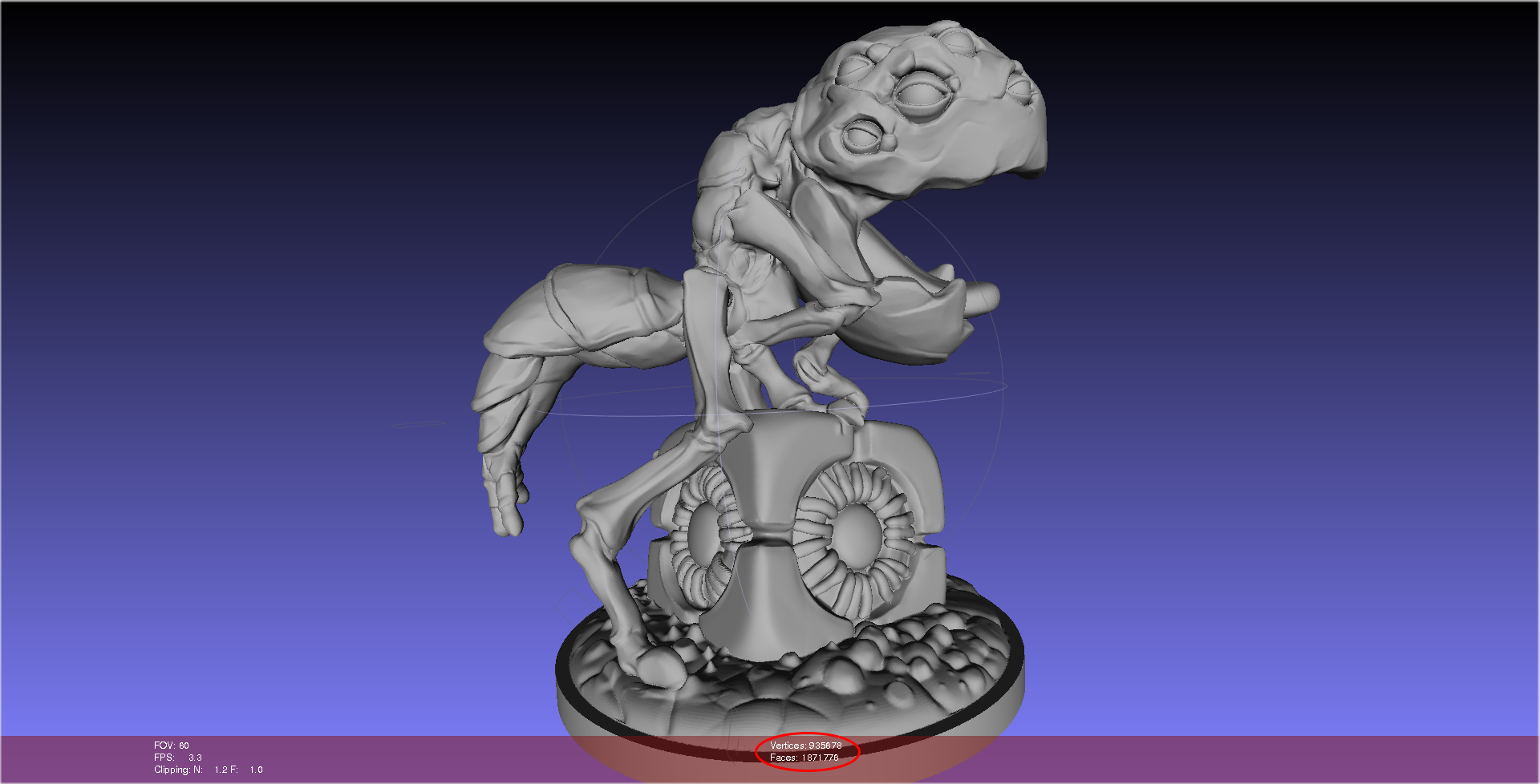
I wanted to print him a monster from the game. An artist at the company,
Aslak, sent me this impressive monster, called a Grue, in a CAD model:
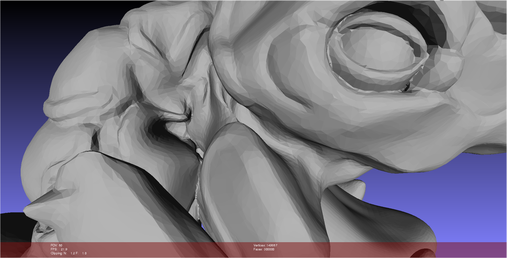
The stl-model of the Grue in Meshlab. It has 1871776 faces and 935678 vertices!
Even though I had a pretty snappy computer to work with, and the latest (1.0.0RC2)
version of Slic3r, slicing
hung time and time again. To make the slice possible at all, I did four things:
Reduced the number of faces
Used the resolution option
Set "number of threads" to 1
Set support material pattern to "rectilinear grid" instead of default "honeycomb"
Thanks to the Slic3r blog for the first three these tips!
Reducing the number of faces was mainly a matter of finding the option
Filters > Remeshing, simplification and construction > Quadratic Edge Collapse Detection
in Meshlab. More details about this is available
here,
but I found the number of faces to be the only important option.
I simplified down to 300k faces without any noticeable artifacts, except when
zooming in really close:
A zoomed in picture of the Grue's head, after the number of total
faces has been reduced to 300000. The resolution is still higher than
that of my 3d printers.
To clean it up, I ran it through a Netfabb repair (locally of course, don't want
to give away Aslak's work to the cloud service).
The resolution option was set to the length travelled my one microstep on
my x- and y-motors on my printer, and number of threads was set to 1, as mentioned
earlier. The figure still wasn't sliceable on my machine though.
The big
breakthrough, and also the big mistake I did then was to change the
support material pattern. Slicing went smooth as a baby's bottom, and I started
to print, but I had forgot to change the pattern spacing! It was left at the
default 2.5 mm spacing, which is ok for a honeycomb pattern, but far too little for
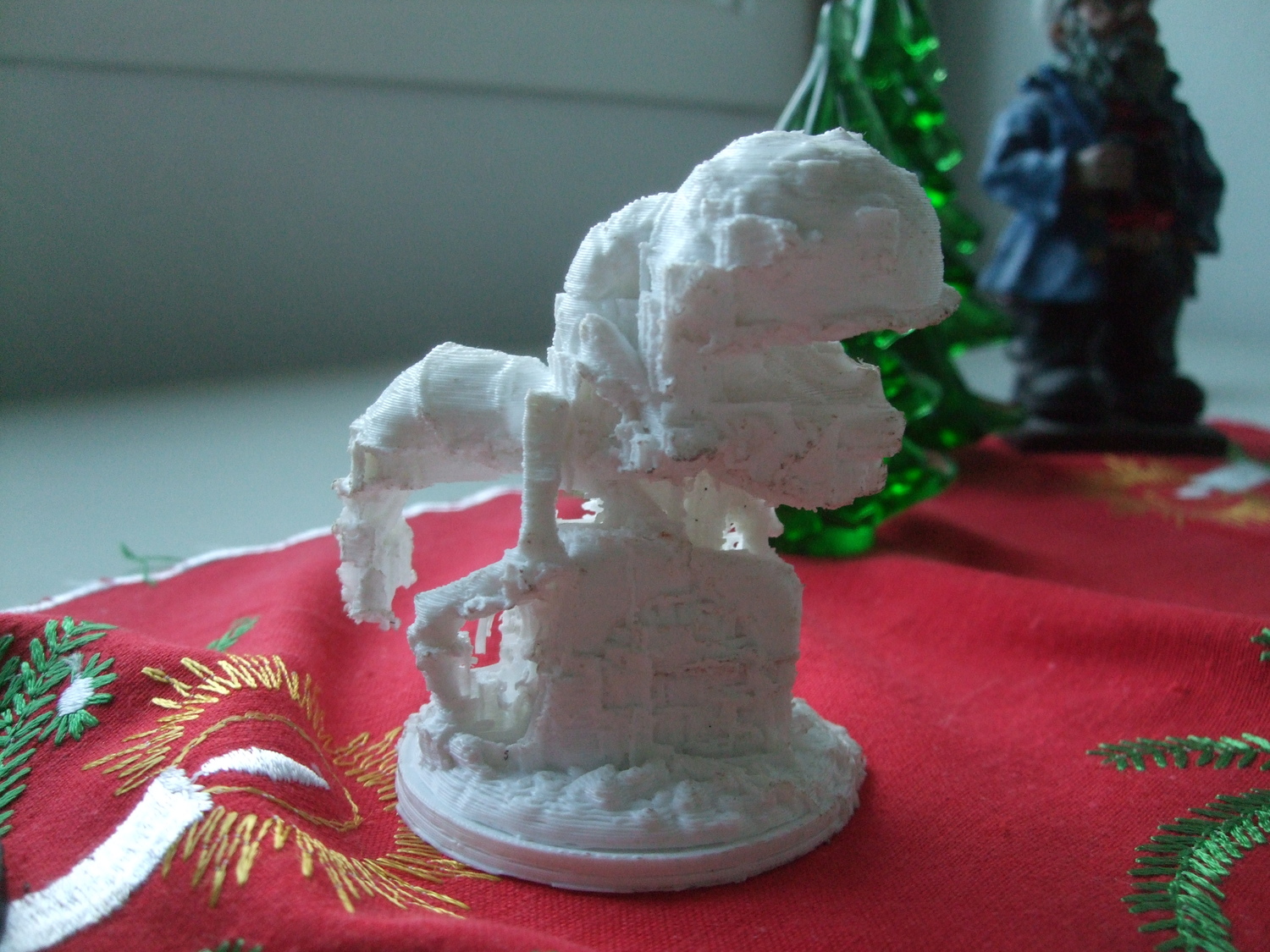
a rectilinear grid. The result was a nearly impermeable clump of
PLA. After about three hours of fighting away support material, this is was what came
out:
The Grue, printed in white PLA and way too much support structures.
The conclusions after making this print were
Use greater pattern spacing than 2.5 mm, when printing rectilinear grid support material.
Don't ever use lots of PLA as support material for a PLA print.
- tobben
Torbjørn Ludvigsen
My brother and his indie game company recently released the awesomely awesome
game Teslagrad. To celebrate,
I wanted to print him a monster from the game. An artist at the company,
Aslak, sent me this impressive monster, called a Grue, in a CAD model:
Introducing the Print Issue Solution Filter web app
15-2-2014
I got an idea the other day, when I was reading a
forum thread.
The RepRap community definitely needs a more effective way to troubleshoot,
than asking random strangers on forums. There should exist a quick troubleshooting
tool for common RepRap problems on the internet.
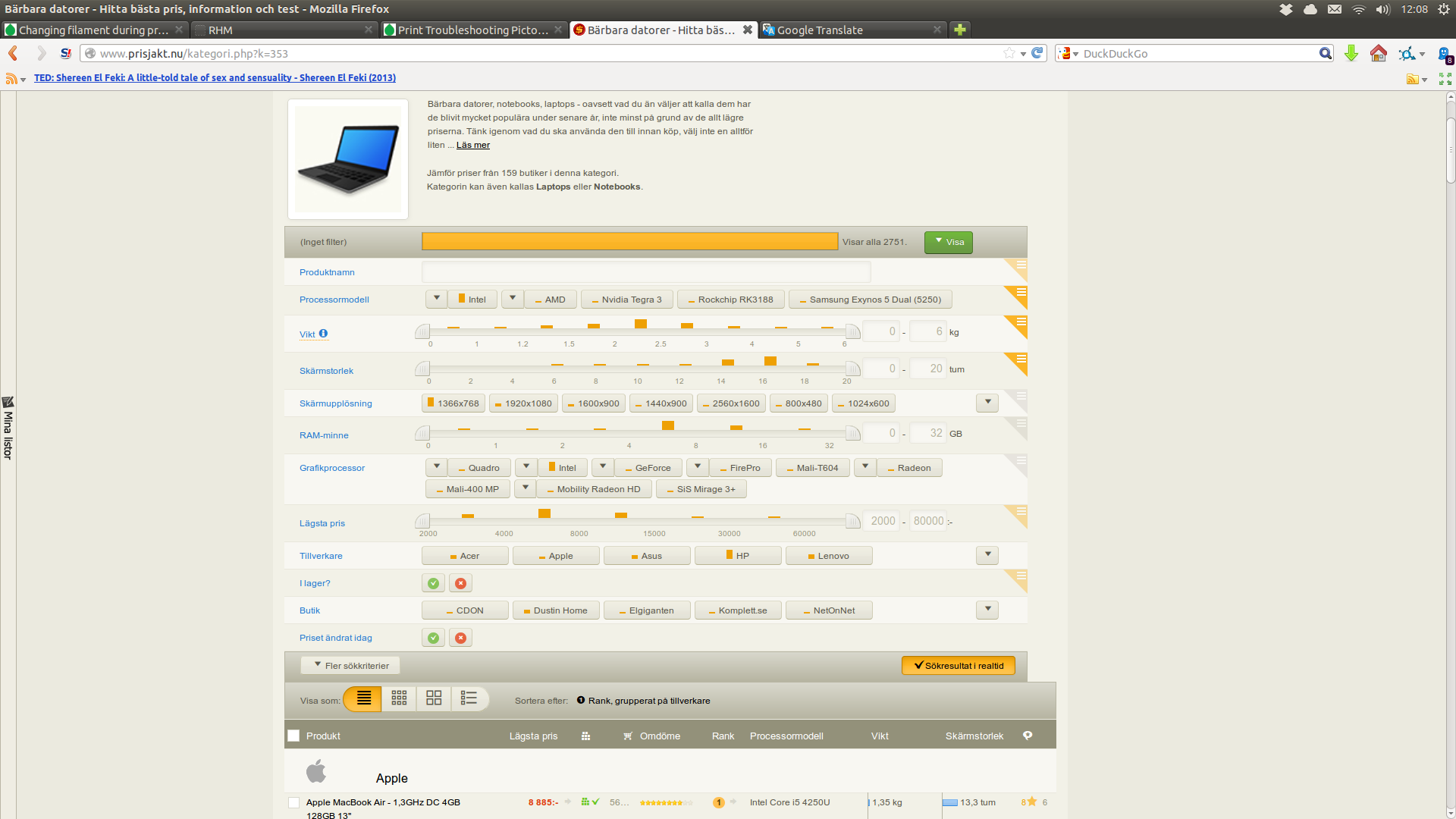
After a short discussion with sluggo, we agreed that web apps that
apply filtering of a database, with live updating, is a very effective
user interface. In particular, we love the interface of shopping sites
like price spy
A screenshot from a shopping sites interface (in Swedish...), letting the
user control a filter on a database of articles.
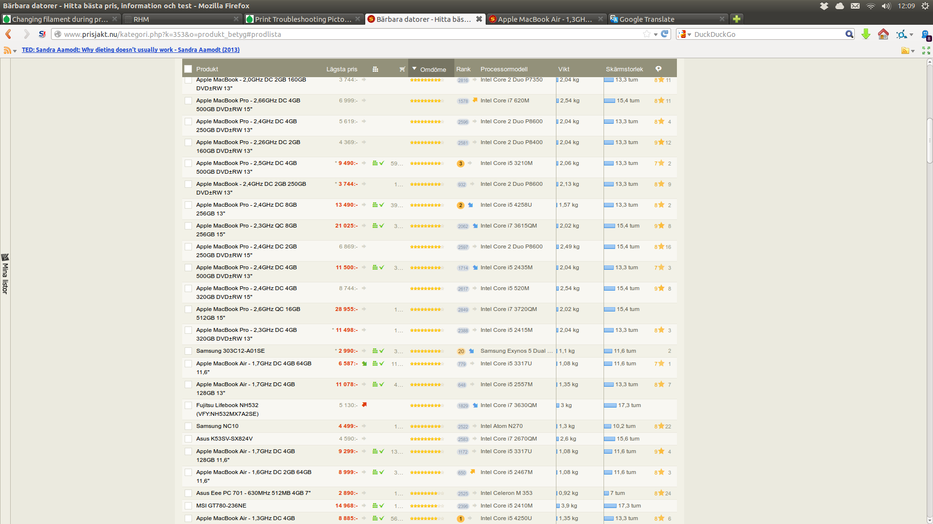
The list of articles, as they are presented to the user.
This list is updated every time the user changes the filtering criteria.
What I mean should be sorted and filtered is a list of mini-articles, like the
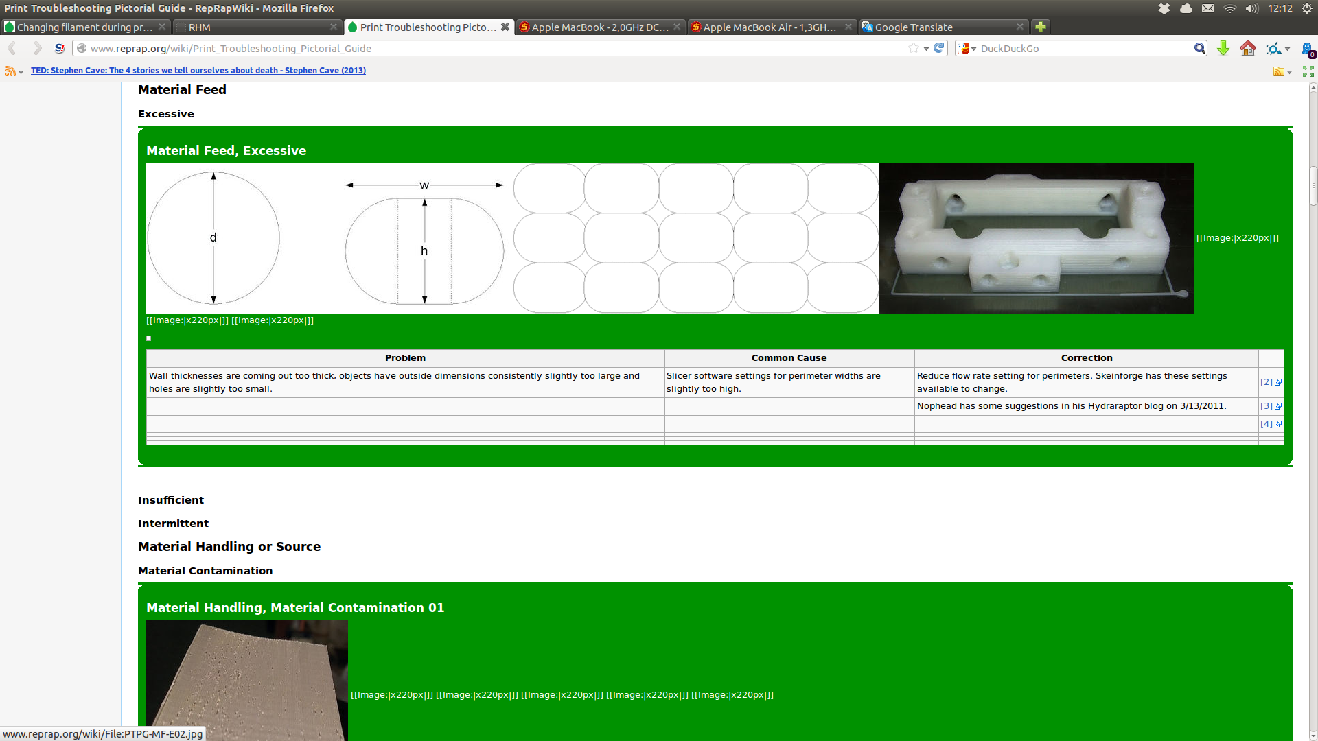
green rectangles on
this wiki page.
The wiki-page contains great information that the community should strive to make
even more accessible.
A wiki-page with a list of mini articles on specific print
issues and their solutions. Very visual, very informative.
I asked in the forum thread if someone knew how to implement a minimalist version
of such a web app, but didn't get any response, so I decided I had to set out to learn it
myself. I really love working with the three structure of Lips-code, so I decided
to take Adam Tornhill's great book
Lisp for the Web
as a starting point. This is where I am today, will be working further tomorrow:
The current state of the Print Issue Solution Filter front page, (15-02-2013).
The current state of the Print Issue Solution Filter
mini article layout, (15-02-2013).
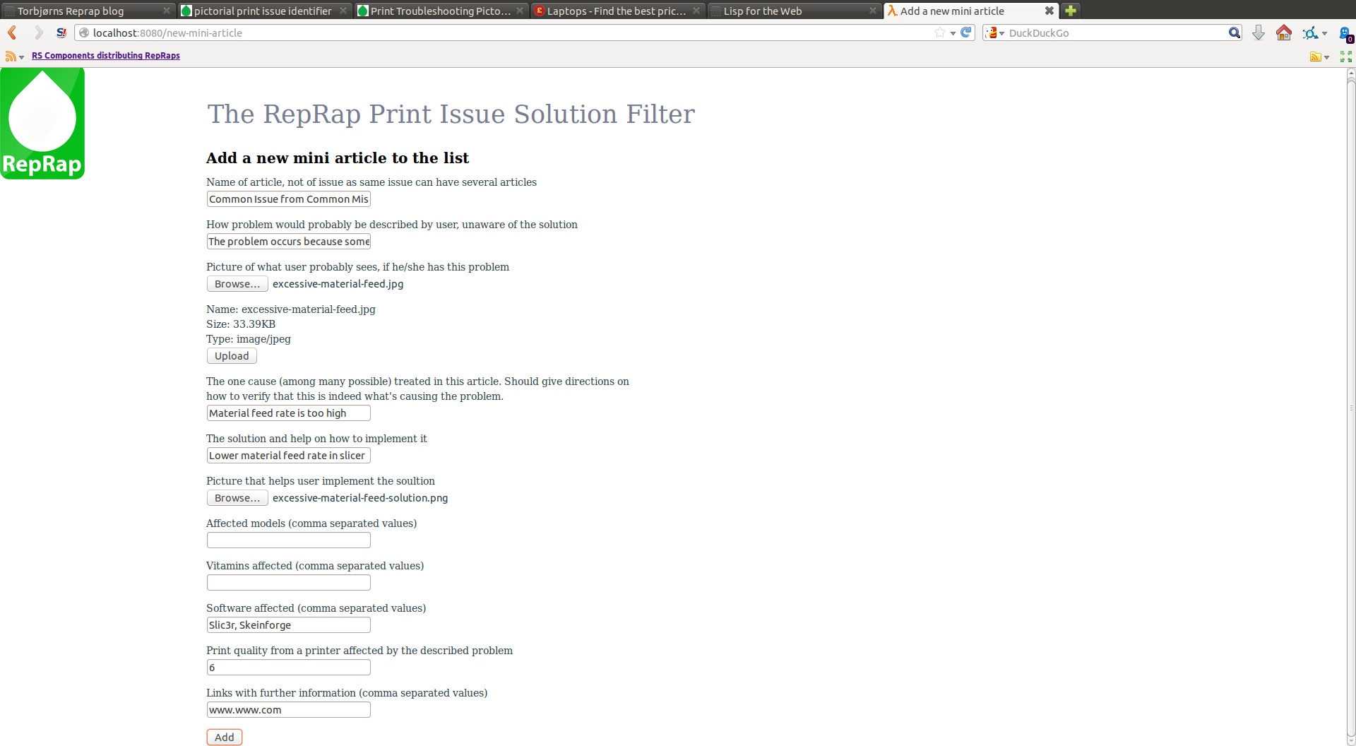
Users should be able to create mini articles, and vote up the good ones.
This screenshot shows the interface to create a mini article. (15-02-2013).
The code is currently 500 lines of messy lisp, but I plan putting it in a
shareable state as soon as possible.
- tobben
Torbjørn Ludvigsen
I got an idea the other day, when I was reading a
forum thread.
The RepRap community definitely needs a more effective way to troubleshoot,
than asking random strangers on forums. There should exist a quick troubleshooting
tool for common RepRap problems on the internet.
After a short discussion with sluggo, we agreed that web apps that
apply filtering of a database, with live updating, is a very effective
user interface. In particular, we love the interface of shopping sites
like price spy
Making custom architrave profiles
7-2-2014
My Mum got a stereo with a docking station that didn't fit her tablet for Christmas.
She still wanted somewhere to put the tablet close to the stereo, so my brother and I made this profile
A custom made architrave profile.
A little too wide in the bottom, but it sits securely.
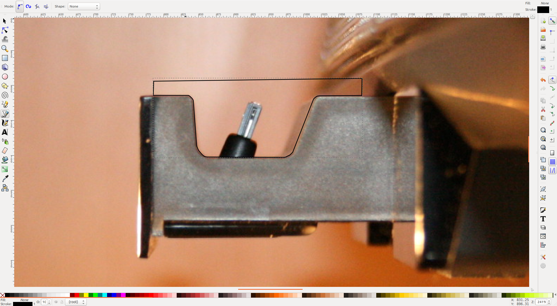
It was made by first taking a photo from the side of the ipod dock, and loading it into Inkscape.
Using the "draw straight lines"-tool (Shift+F6), a profile similar to this
(I didn't save the original) was drawn:
Drawing the profile in Inkscape.
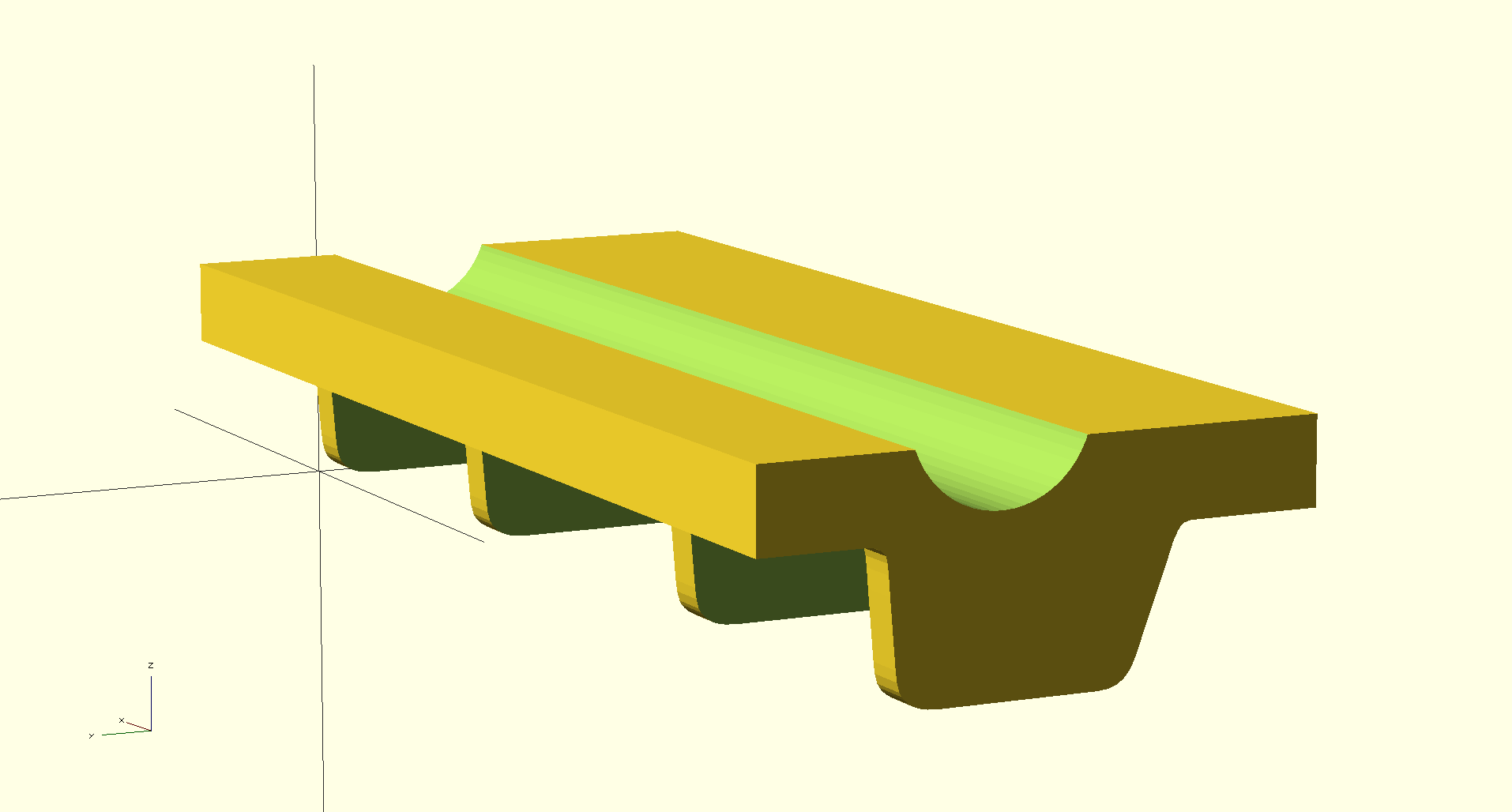
The background picture was deleted after this, and a OpenSCAD dxf
(thanks again to the plugin) was exported.
The dxf was then linear_extruded, and four cubes and one cylinder was cut out of it to
produce the following shape
The model of the architrave, made and rendered in OpenSCAD.
Torbjørn Ludvigsen
My Mum got a stereo with a docking station that didn't fit her tablet for Christmas.
She still wanted somewhere to put the tablet close to the stereo, so my brother and I made this profile
CAD'ing support structures when PLA printing
5-2-2014
I recently had to print out some small overhangs with PLA. After a previous
PLA support material experiment, I decided to try
to model the support structures myself (I was inspired by one of nophead
wonderful blog Peel-able support?.
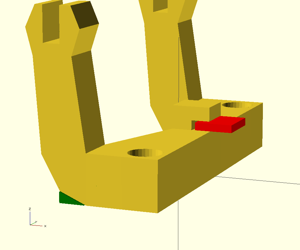
In OpenSCAD, it looked like this:
A version of y_end_back.stl from Smartfriendz' excellent
Smartrap repo with
my added supporting blocks in red and green.
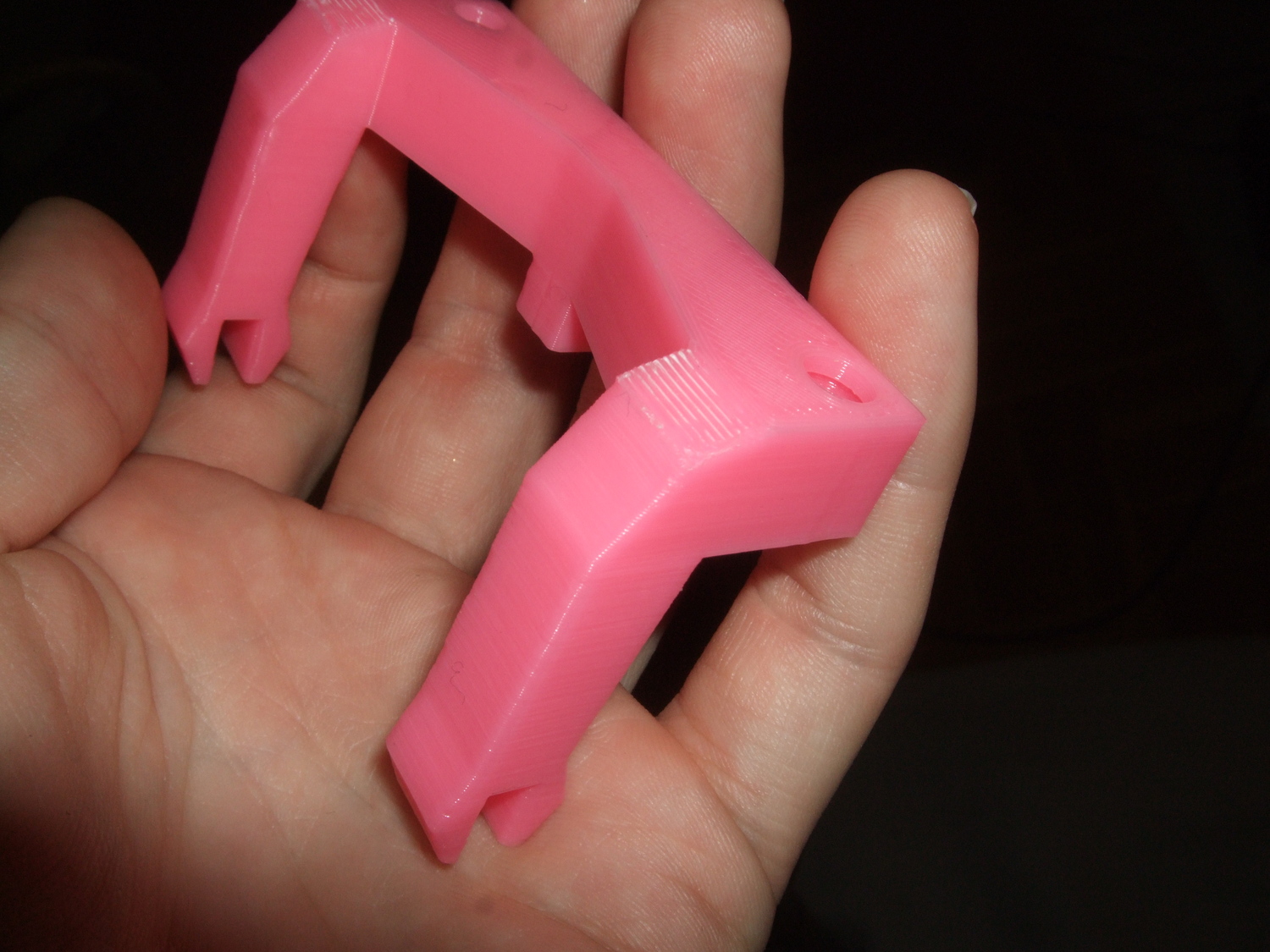
I found that ca 0.15 mm vertical gap gave the best results with my current
plastic and slic3r settings. This will of course vary wildly depending
on plastic type, geometry, layer height, extrusion width and so on.
I found the results satisfying:
Scars after removing CAD'ed support material.
Scars after removing CAD'ed support material.
I will definitely CAD my own support material again, when only PLA is
available as print material.
- tobben
Torbjørn Ludvigsen
I recently had to print out some small overhangs with PLA. After a previous
PLA support material experiment, I decided to try
to model the support structures myself (I was inspired by one of nophead
wonderful blog Peel-able support?.
In OpenSCAD, it looked like this:
Minor Reprappro Mendel tweaks
4-2-2014
I was recently preparing some large prints with my parent's Reprappro Mendel,
and decided to do a bunch of minor tweaks. First, I went to Reprappro's own
documentation to search for inspiration, and they had prepared
this
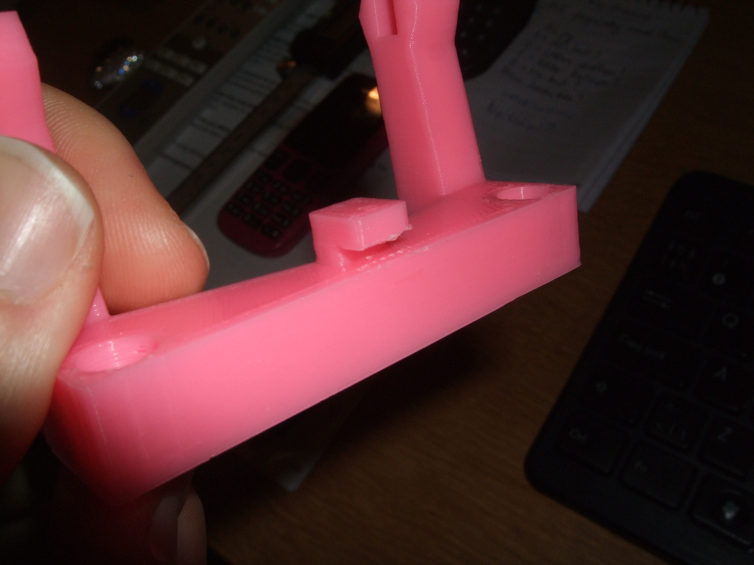
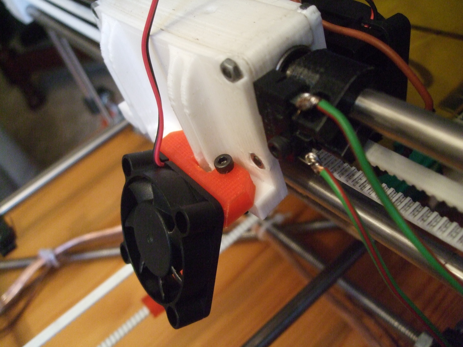
=D. I decided to to both the "Fan mount":
A 40 mm fan mounted on a Reprappro Mendel.
and the "Alternative positions for extruders":
The alternative extruder position of choice on my parent's Reprappro Mendel.
This gave ca 2 cm extra print height and was done in 15 minutes. No software settings
needed to be changed, no wires needed to be disconnected. Using only two
mounting points is definitely rigid enough.
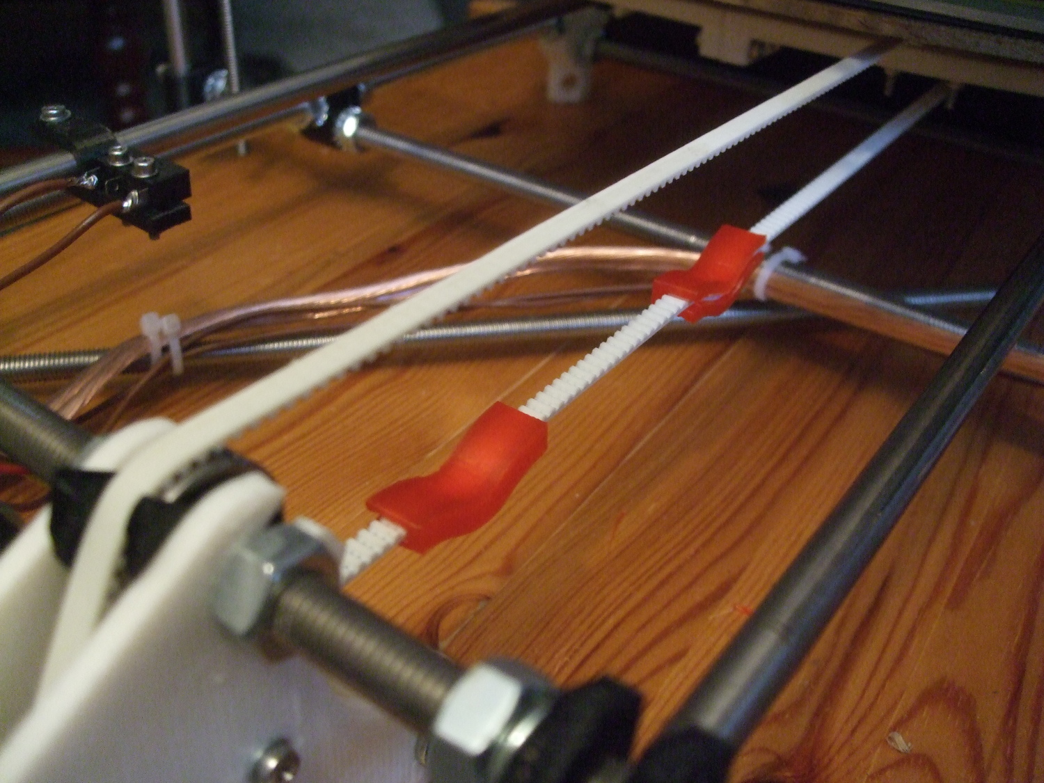
I haven't found any elegant way to tension the y-belt on this design easily.
At least I found a way that doesn't consume a lot of time or concentration,
the belt tensioner
by Reuben on Thingiverse. This is how it looked
Not elegant, but pragmatic belt tensioners in action.
- tobben
Torbjørn Ludvigsen
I was recently preparing some large prints with my parent's Reprappro Mendel,
and decided to do a bunch of minor tweaks. First, I went to Reprappro's own
documentation to search for inspiration, and they had prepared
this
=D. I decided to to both the "Fan mount":
Sourcing a Reprappro Mendel in Larvik. The rest
3-2-2014
To actually make the finishing touch to make the Mendel operative was much
more difficult than expected. Troubles with electronics took most of the extra
time. The
Melzi
I had found cheap on ebay had the wrong sort of connectors
(not screw connectors), and an Atmega 644p instead of an Atmega 1284p.
The standard Melzi stepper drivers, A4988, also requires active cooling for currents
greater than 1 A.
For reasons I still don't understand, we could only control
the motors to turn if we
sat velocities really low. Maybe Marlin and Pronterface disagreed on whether to
use absolute or relative coordinates, causing the movements sent from pronterface
to be interpreted as impossibly fast (due to voltage rise times etc) by Marlin?
In the end, one of the A4988's and the heat bed transistor burned because of
too high motor current a frayed untinned HB connection respectively).
I decided to buy a completely new
Melzi from a new source (reprap.me), to tin all connectors and to only use motor
currents less than 1 A.
The cheap Melzi, before it burned.
The new Melzi board had two problems though:
Z-homing didn't work
Extruder motor just stuttered
The z-homing problem looked like
this (youtube video).
Issuing M119 (Get Endstop Status) showed that Marlin thought the z-switch was
always open. It was solved with a kamikaze soldering directly on the Atmega's one
leg. It is described in an
earlier post and in this
forum thread.
The extruder motor was luckily a problem i software. The solution is described
in this
forum thread.
These troubles ceirtanly slowed the project down, and only one day was left
of my summer holydays to teach my parents how to use the machine. The first
print was a handle to a dipstick. It printed
nicely like this (youtube video). And
we soon went on to print a Julia vase (desperate attempt to convince Mum this
machine is of any value:
The self sourced Mendels' second print.
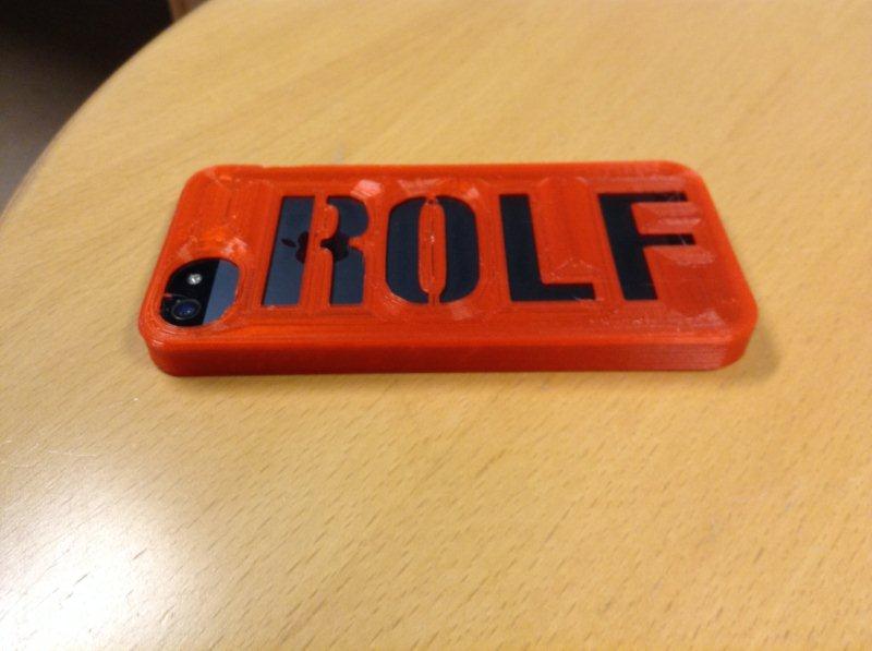
After a couple of weeks into the semester, Dad mentioned on the phone
wanted to try it out to print a smartphone case. I went on Thingiverse and
found the
Monogrammed iPhone case
made by TheNewHobbyist. I modified it, sliced it, emailed the gcode
and got this picture from Dad a couple of days later:
The first print my Dad did with his Reprappro Mendel.
I'm as proud as he is.
Success! I'm very excited to see how my parents relationship to the
Reprap develops. Thanks for listening.
- tobben
Torbjørn Ludvigsen
To actually make the finishing touch to make the Mendel operative was much
more difficult than expected. Troubles with electronics took most of the extra
time. The
Melzi
I had found cheap on ebay had the wrong sort of connectors
(not screw connectors), and an Atmega 644p instead of an Atmega 1284p.
The standard Melzi stepper drivers, A4988, also requires active cooling for currents
greater than 1 A.
Sourcing a Reprappro Mendel in Larvik. Weekend 1 and 2
2-2-2014
At this point, my summer job in Oslo had started, so I could only work
during weekends. Pace naturally slowed down. This gave the postal service time
to catch up. I received endstop switches, glass bed, 623-bearings, hot-end,
XLR-plug, stepper motors, the Melzi board and filament. Unfortunately, the filament I received had the wrong
diameter, so the order must be placed again... Ordering is hard and depends on
a lot of unknown factors.
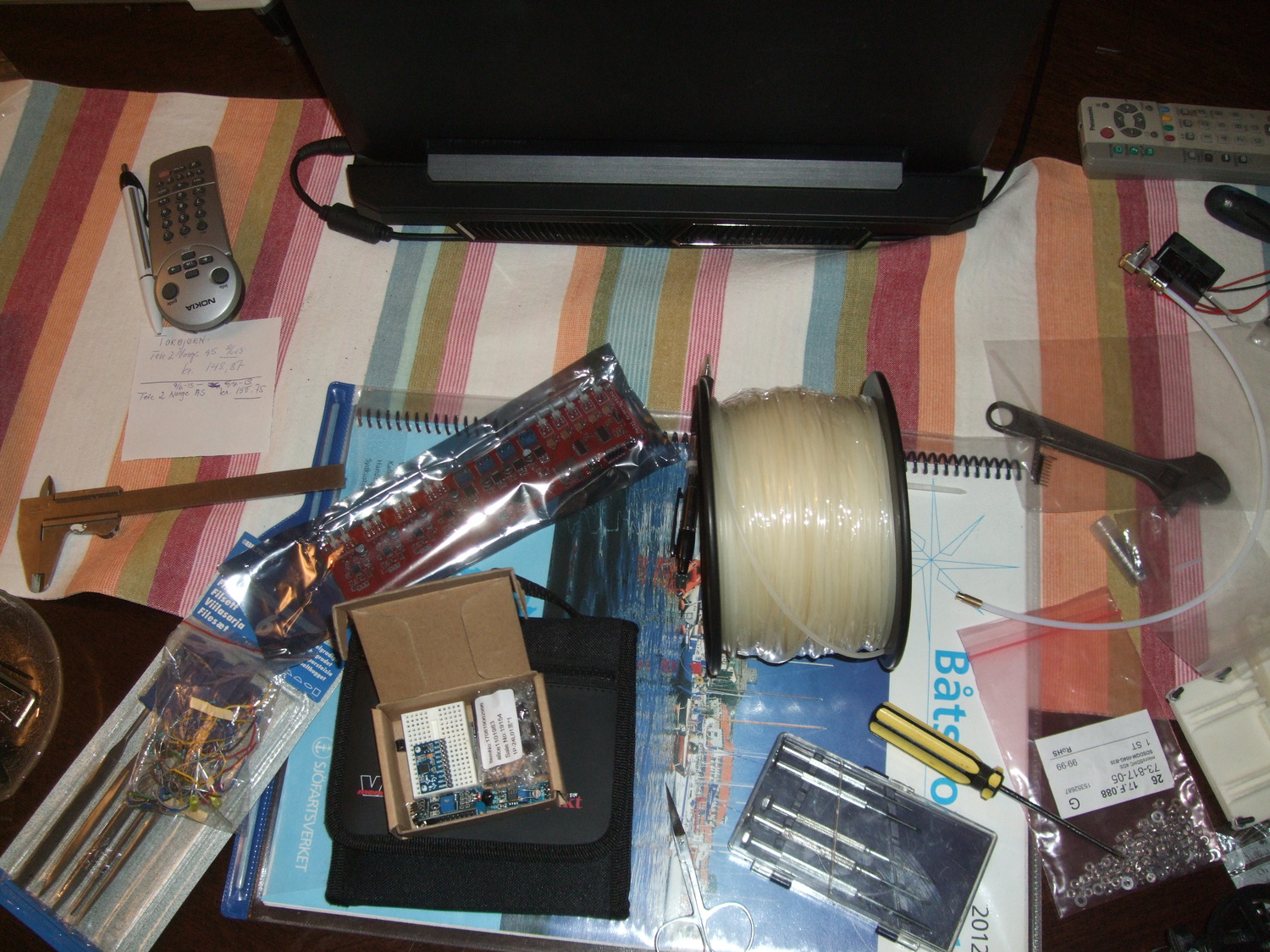
Coffee table used as workbench with hot end, filament, Melzi board and various other things.
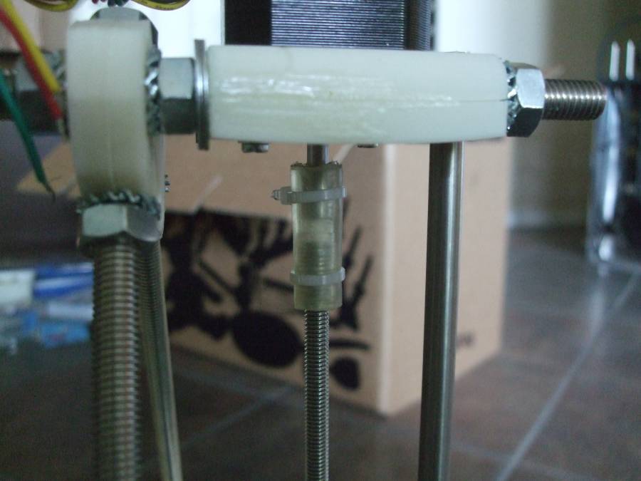
Since I used a M6 rod for the z-axis, and the motor shaft had 5 mm shafts, I
couldn't use a uniform tube as linkage. The solution I found was to drill
out a couple of glue gun patrons. I described them in an
earlier post.
- tobben
Torbjørn Ludvigsen
At this point, my summer job in Oslo had started, so I could only work
during weekends. Pace naturally slowed down. This gave the postal service time
to catch up. I received endstop switches, glass bed, 623-bearings, hot-end,
XLR-plug, stepper motors, the Melzi board and filament. Unfortunately, the filament I received had the wrong
diameter, so the order must be placed again... Ordering is hard and depends on
a lot of unknown factors.
Sourcing a Reprappro Mendel in Larvik. Day 6 and 7
1-2-2014
Not much could be done day 6. Managed to make an insulating sheet with a handsaw
and a drill from the dxf on Reprappro's Mendel repo on Github:
Almost finished insulating sheet.
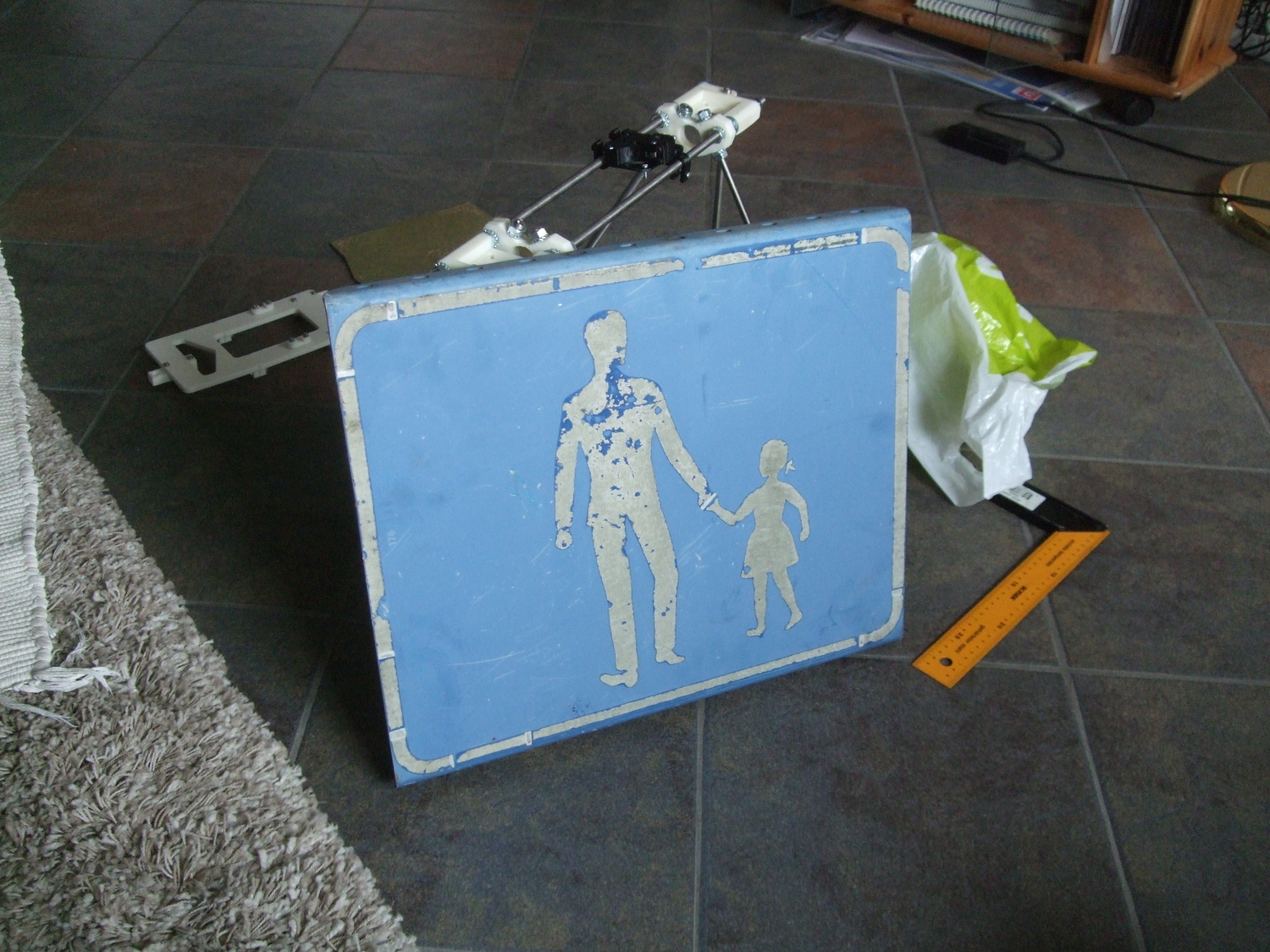
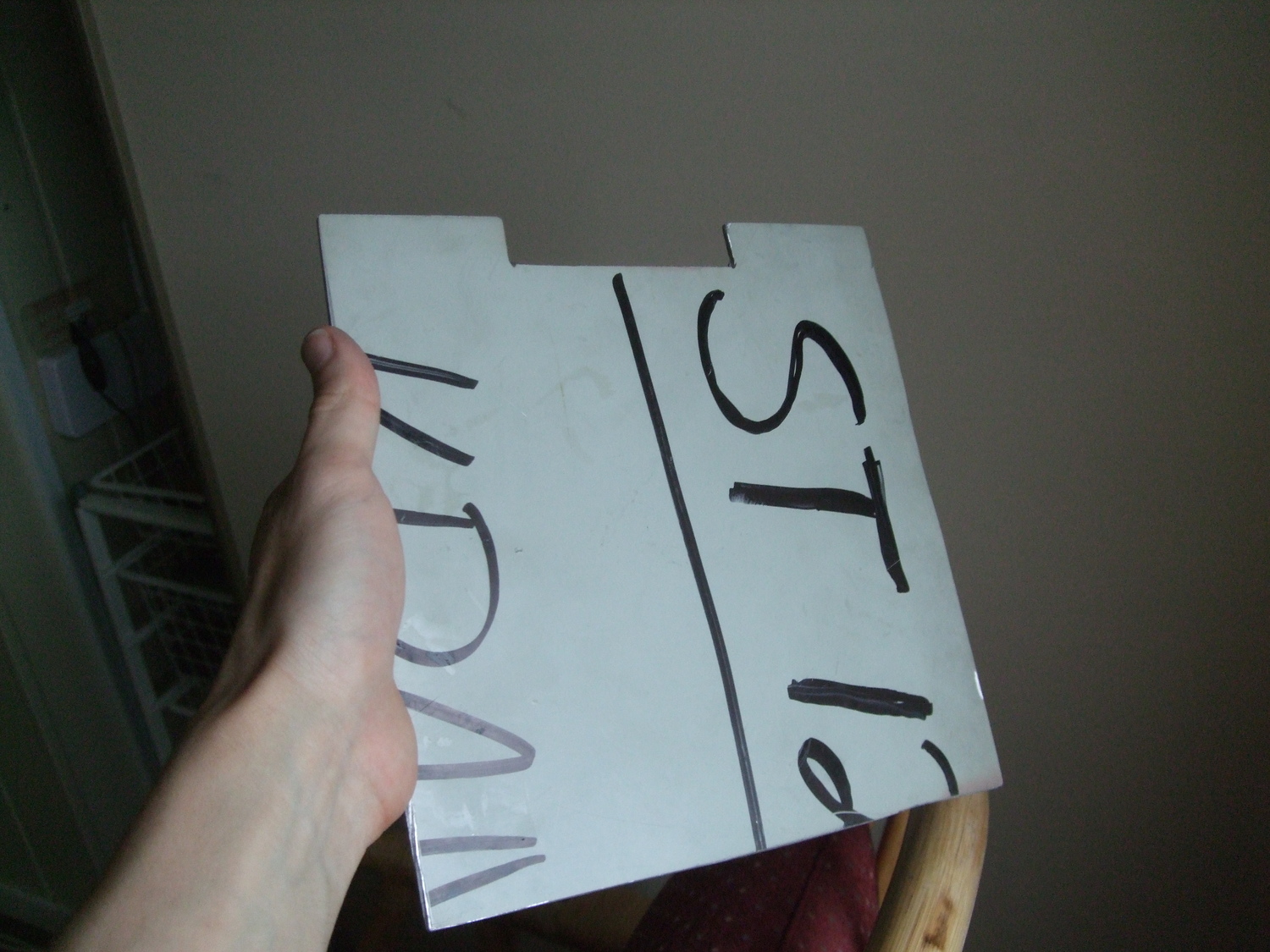
At day 7 dad came home from work with an old aluminum traffic sign!
I cut it out to a heat spreader (except the corner holes).
A used old traffic sign, exactly the right thickness and flatness to serve as a heat spreader.
Drawing the outline from the dxf supplied by Reprappro and cutting it with
a grinder was fairly straight forward.
The back side of the almost finished heat spreader cut out of a traffic sign.
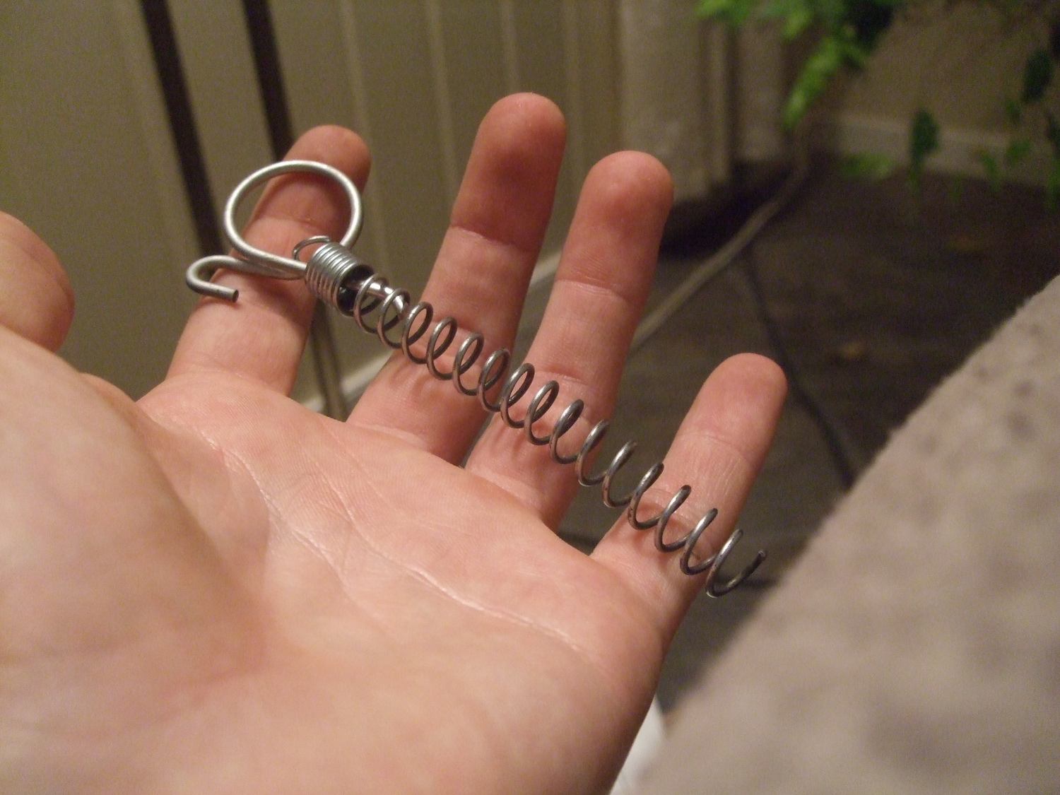
I was lucky to do this project in a house with lots of hardware stuff lying
around. For example, I could stretch out a old unused springs I found, and
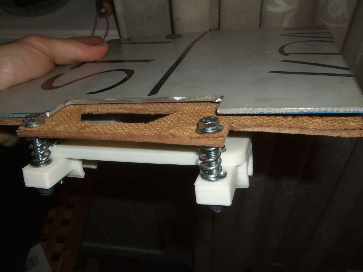
use them to hold up the insulator + heat spreader:
A spring I made use of.
Springs on the y-carriage.
- tobben
Torbjørn Ludvigsen
Not much could be done day 6. Managed to make an insulating sheet with a handsaw
and a drill from the dxf on Reprappro's Mendel repo on Github:
VRR firmware and a different way of communicating with 3d-printers
1-2-2014
I've started working on a, as far as I know, new type of firmware.
The main idea behind it is to minimize the need of processing power on
the actual printer by reducing it to a slave that only relays low-level commands from the computer.
Of course it will have to take care of some timing and buffering but that's about it.
Since this type of protocol is not compatible with the current G-Code
based one I'm also working on a driver that will emulate some generic G-Code receiving printer to make it work as a drop-in
replacement.
The upsides I see with the master-slave vs client-printer model are many,
first of all unless you plan on equipping you printer with a >100$
cpu your computer will always be better at doing pretty much all the calculations needed for a print -
thats why we do the slicing on it!
Another key reason why I found the idea worth exploring is the much improved debugging capabilities,
many G-Codes instructs the printer to perform several actions (e.g. G28 - home all)
if any of these fail no further information than that the complete instruction failed is given.
Now, using a printer that exports information about what pins it has
and what they do and then simply receives ctrl-msgs pertaining those pins,
i.e. a semi-transparent hardware abstraction protocol (kinda directly controlling the pins on the board using ctrl-msgs)
or StAHP,
each action can be performed with minute control giving the user the ability to pinpoint exactly when and where the printer
fails.
Having this type of control over the printer also means pausing,
aborting, adding or subtracting parts (to/from) a running print-job will be much easier.
A basic printer-computer handshake would look something like this (M - master/computer, S - slave/printer)
format: seqno, sender: <msg>
00, S: <init printer>				// handshake init
00, M: <printer confirm>
01, S: <printer id>
01, M: <printer id confirm>
// M checks if it has Ss ctrls cached, if not:
02, S: <N controls installed>			// # controls on printer (N)
02, M: <ctrls confirmed>
03, S: <ctrl 1: type>				// type of ctrl 1 (stepper motor, fan ctrl, etc)
03, M: <ctrl 1 type confirm>
04, S: <ctrl 1: func>				// function of ctrl 1 (e.g. type = motor, func could be x/y/z-axis)
04, M: <ctrl 1 func confirm>
// further info about func exchanged
05, S: <ctrl 1: M pins>				// # pins for ctrl 1 (M)
05, M: <ctrl 1 pins confirm>
06, S: <ctrl 1, pin 0: func>			// function of pin 0 on ctrl 1
06, M: <ctrl 1, pin 0, func confirm>
07, S: <ctrl 1, pin 0: min>			// min value of pin 0
07, M: <ctrl 1, pin 0 min confirm>
08, S: <ctrl 1, pin 0: max>			// max value0
08, M: <ctrl 1, pin 0, max confirm>
... // this continues for all pins on all ctrls
R0, S: <ctrl N, pin K-1: max>			// where K is the number of pins on ctrl N
R0, M: <ctrl N, pin K-1, max confirm>
R1, S: <max bufsz: L>				// # ctrl-msgs that fit in the printers buffer
R1, M: <bufsz confirm>
R2, S: <awaiting action>
R2, M: <awaiting action confirm>
... // M can now start controlling the printer
As seen the handshake time can be reduced quite much if the master has a cache of the printers ctrls.
As such a cache (config) file could be easily produced when writing/porting the firmware
to different boards hopefully the start-up time of printers using this type of firmware
can be reduced to almost zero.
This project is still in its infancy and the driver will probably not be ported to windows until the first stable version.
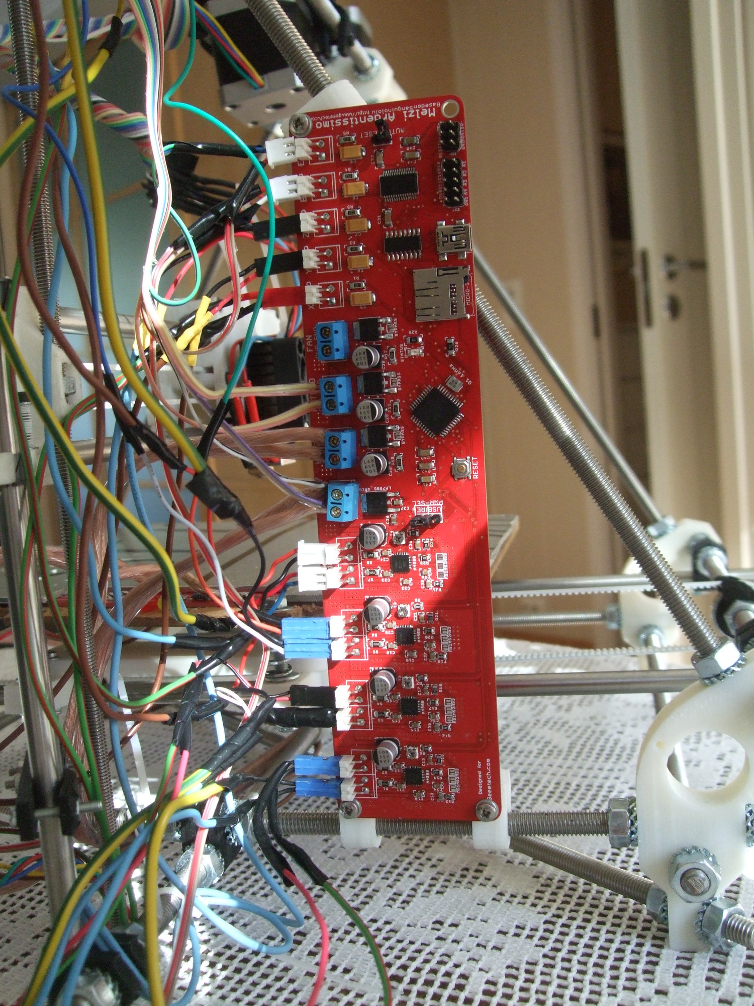
I'm using a left over Melzi Ardentissimo v.1 board from geeetech.com
to develop it so that type of board will probably be the first one to have a usable beta.
// sluggo
Torbjørn Ludvigsen
I've started working on a, as far as I know, new type of firmware.
The main idea behind it is to minimize the need of processing power on
the actual printer by reducing it to a slave that only relays low-level commands from the computer.
Of course it will have to take care of some timing and buffering but that's about it.
Since this type of protocol is not compatible with the current G-Code
based one I'm also working on a driver that will emulate some generic G-Code receiving printer to make it work as a drop-in
replacement.
Making simple twisted vases
31-1-2014
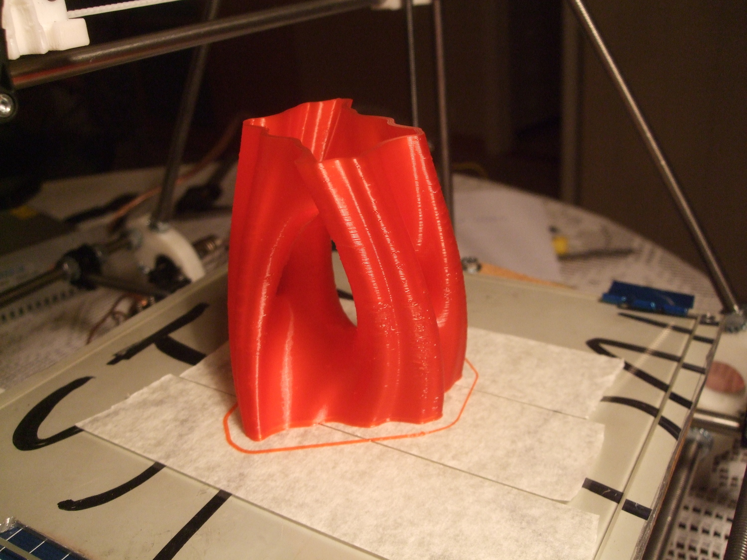
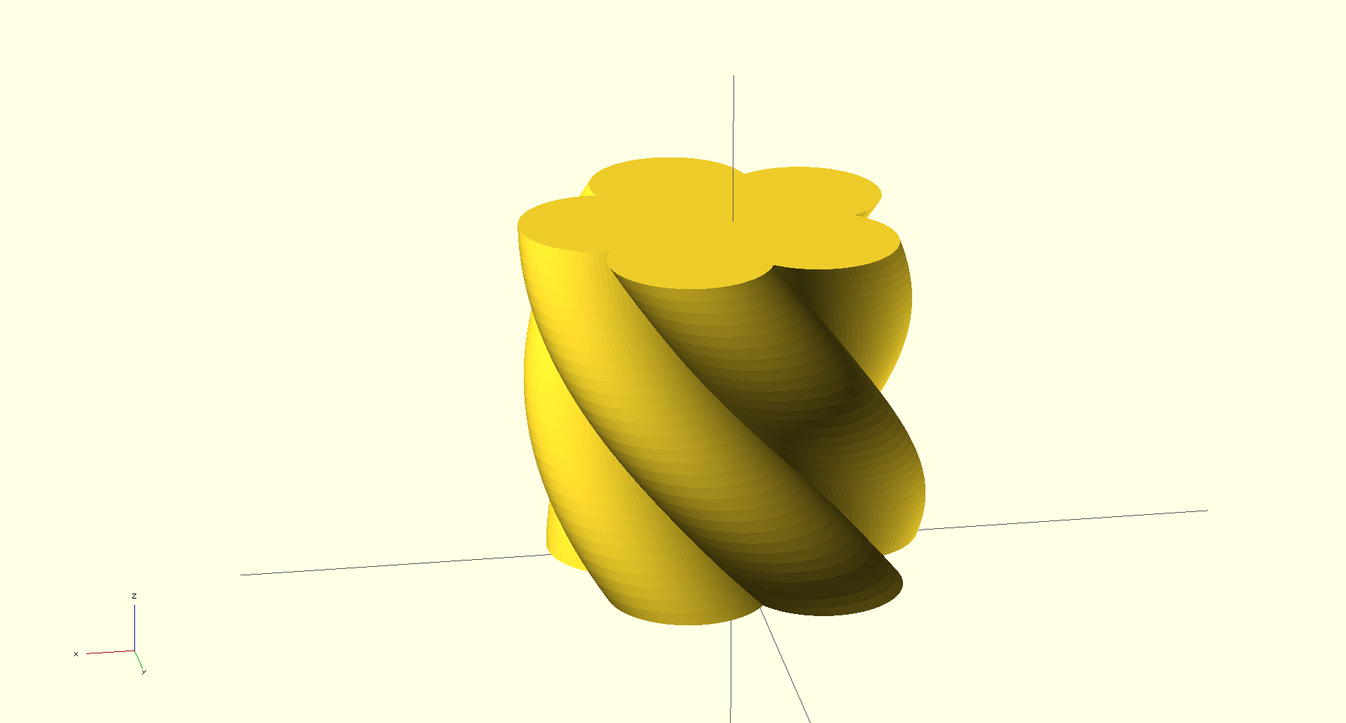
I recently printed some twisted vases.
They were drawn by using an
svg flower icon,
LibreCAD, Inkscape (with polymaker's
plugin)
and LibreCAD.
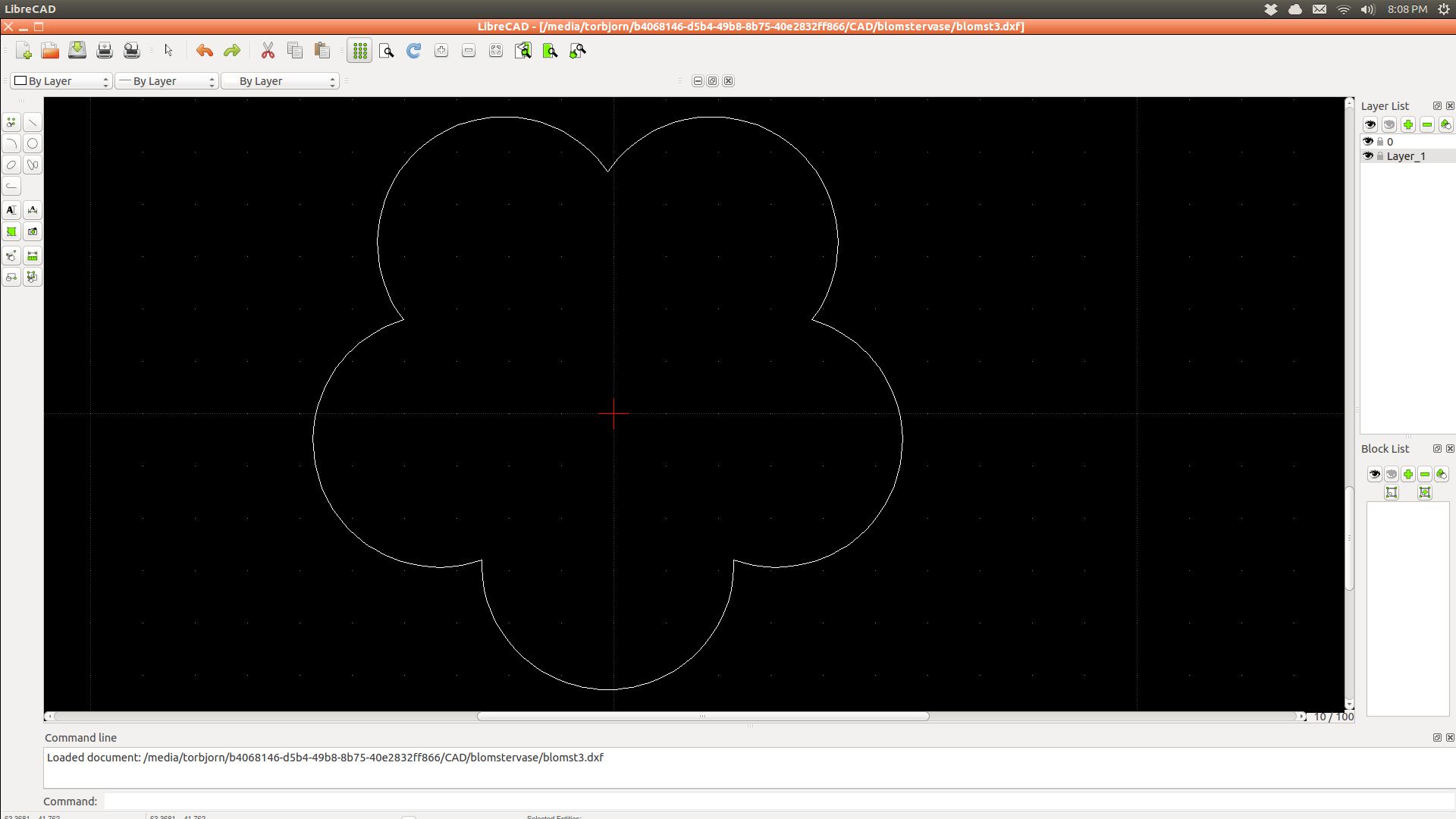
I first opened the svg in Inkscape and saved it as "OpenSCAD DXF Output" (thanks to the plugin).
I then removed unwanted edges, scaled it and centered it in LibreCAD.
Screenshot from LibreCAD, only outline of the original svg remaining.
In OpenSCAD, the line of code to extrude the vase was
Screenshot from OpenSCAD, ready to export the stl-file.
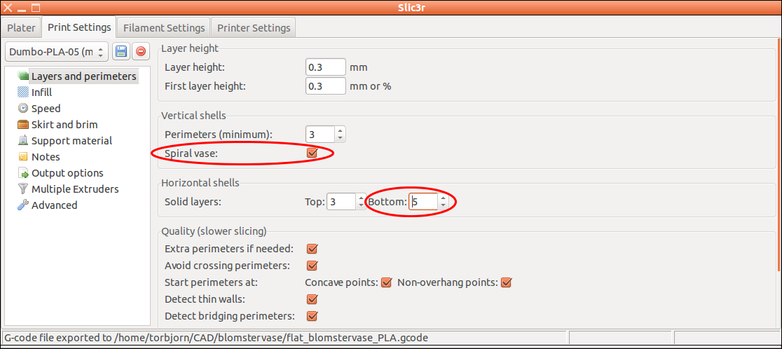
I then exported as stl and imported it into Slic3r. To slice it a spiral vase, you need to tick a box
and choose number of bottom layers. The only other relevant setting is extrusion width.
Screenshot from Slic3r, with relevant settings highlighted.
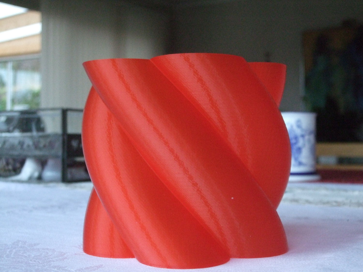
I used an extrusion width of 0.83 mm for this large vase, to make it sturdy. Use lots of plastic
(a fairly large extrusion multiplier or a similar setting) if you want the bottom to be water tight.
Here is the result
I also experimented with rendering and slicing it on my 7 year old laptop.
To make the laptop handle it, I had to remove 75 % of the line segments in the dxf. I did this by opening
it in Gvim, and removing every second coordinate-pair with a little macro, twice.
The coordinates are preceded by a line saying AcDbPolyline. Every x-coordinate is preceded
with a line saying 10, and every y-coordinate is preceded by a line saying 20.
To be able to do the CGAL compile and render in OpenSCAD, I also reduced the number of linear-extrude-slices.
I also found I had to use a SD-card directly in the Melzi to get fast enough
data transmission of the gcode.
The result is
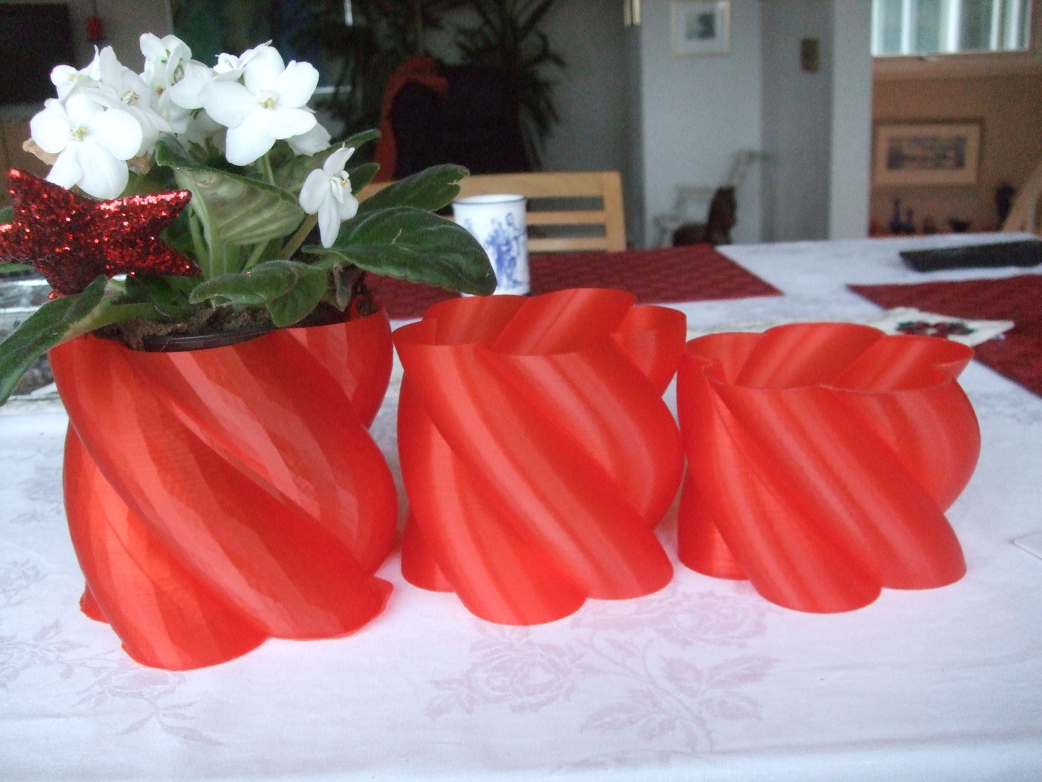
the leftmost and biggest (I also scaled it up a bit) vase on this picture
A little vase family.
When printing the rightmost one, my glue gun patron z-coupling solution failed.
An improvised z-coupling made out of a drilled out glue gun patron.
It has the advantage that one can drill out the desired diameter in either end, so threaded
z-rods thicker or thinner than the shaft can be used.
It turned out that the friction between the tube and the motor shaft was too low.
The fix was just to change the upper zip tie with a hose clamp.
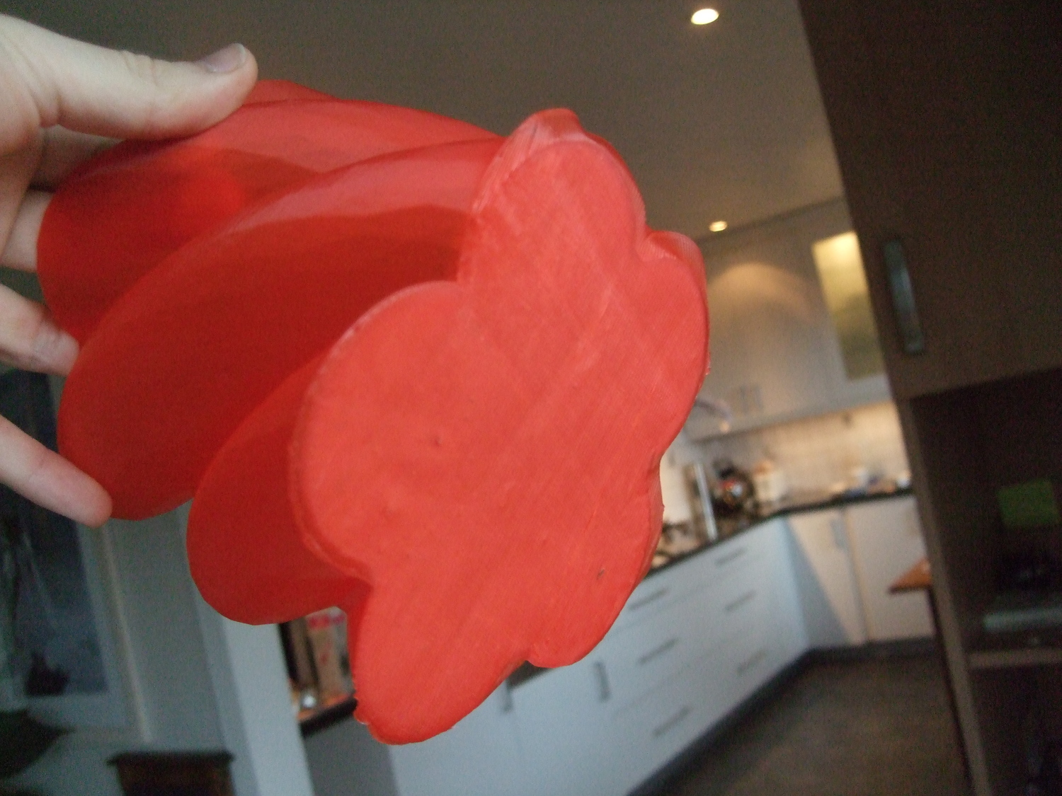
The leftmost vase on the picture above has a little excessive edge on the bottom.
This is due to a failed attempt to make it water tight, by welding a new
bottom layer to it. To make this weld successful, I think you need to press
it against surface hotter than the one I used, for a very short time (~ 1 sec). Aluminum
foil in a hot frying pan might do the trick, I will try that next time. Here's
how it looks from below
A failed attempt to make a vase water tight by welding
a new first layer onto it. Was pressed against a hot glass fireplace door
covered with aluminum foil for about 10 seconds
- tobben
Torbjørn Ludvigsen
I recently printed some twisted vases.
They were drawn by using an
svg flower icon,
LibreCAD, Inkscape (with polymaker's
plugin)
and LibreCAD.
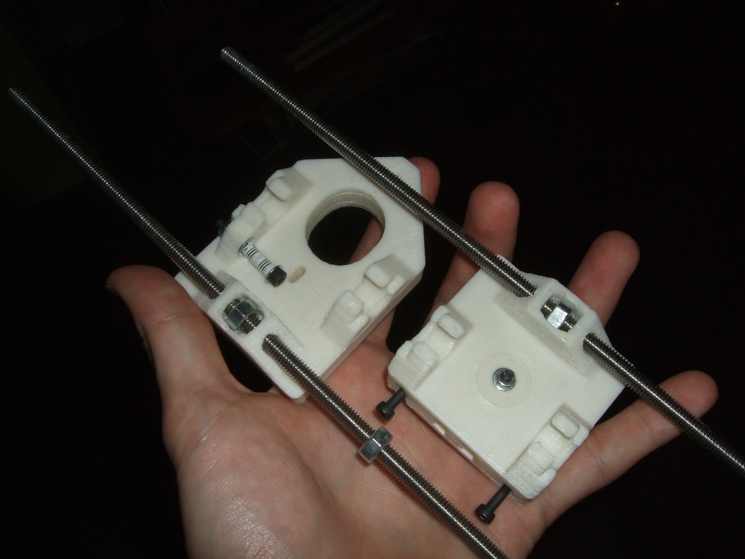
Sourcing a Reprappro Mendel in Larvik. Day 5
31-1-2014
For the z-axis, I had chosen M6 instead of M5, because I had a pair of M6 lying
around. Making them, and their nuts fit into the printed x-motor-bracket and
x-idler-bracket was a PITA, involving lots of difficult sanding. Even getting
the M3 nuts down into the nut traps was really difficult and time consuming
because of the small holes and overall low quality of my printed parts.
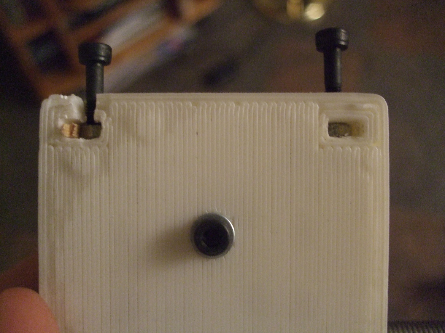
How my x-idler-bracket looked when I finally had the M3 nuts fit
tightly in the nut traps. Just calibrating
sigrid
properly before printing them would have saved so much time.
Eventually, I had x-brackets with nuts fit super-tight which is nice.
My finished x-idlerbrackets with M6 threaded rods instead of M5 ones.
Finally, I got 623 bearings (1.7 NOK each!) from Ebay, and Igus clip bearings
and a hobbed bolt for the Mini extruder from eMakershop. I'm quite surprised that
Igus clip bearings are used. They are pretty hard to find, even on the internet,
and they seem easy to replace with a home made alternative. I would definitely
replace them with printed nylon bushings in my own design.
- tobben
Torbjørn Ludvigsen
For the z-axis, I had chosen M6 instead of M5, because I had a pair of M6 lying
around. Making them, and their nuts fit into the printed x-motor-bracket and
x-idler-bracket was a PITA, involving lots of difficult sanding. Even getting
the M3 nuts down into the nut traps was really difficult and time consuming
because of the small holes and overall low quality of my printed parts.
Sourcing a Reprappro Mendel in Larvik. Day 4
30-1-2014
Today was a better shopping day. A local hardware store cut me the smooth rods
I needed for 25 NOK. "And that gives us huge margins", was the owners comment
on the price, so I guess smooth rods are really cheap when you buy in large
quantities. If I had a garage, I would try to do that.
Thanks to Stensland's Workshop for supplying and cutting smooth rods!
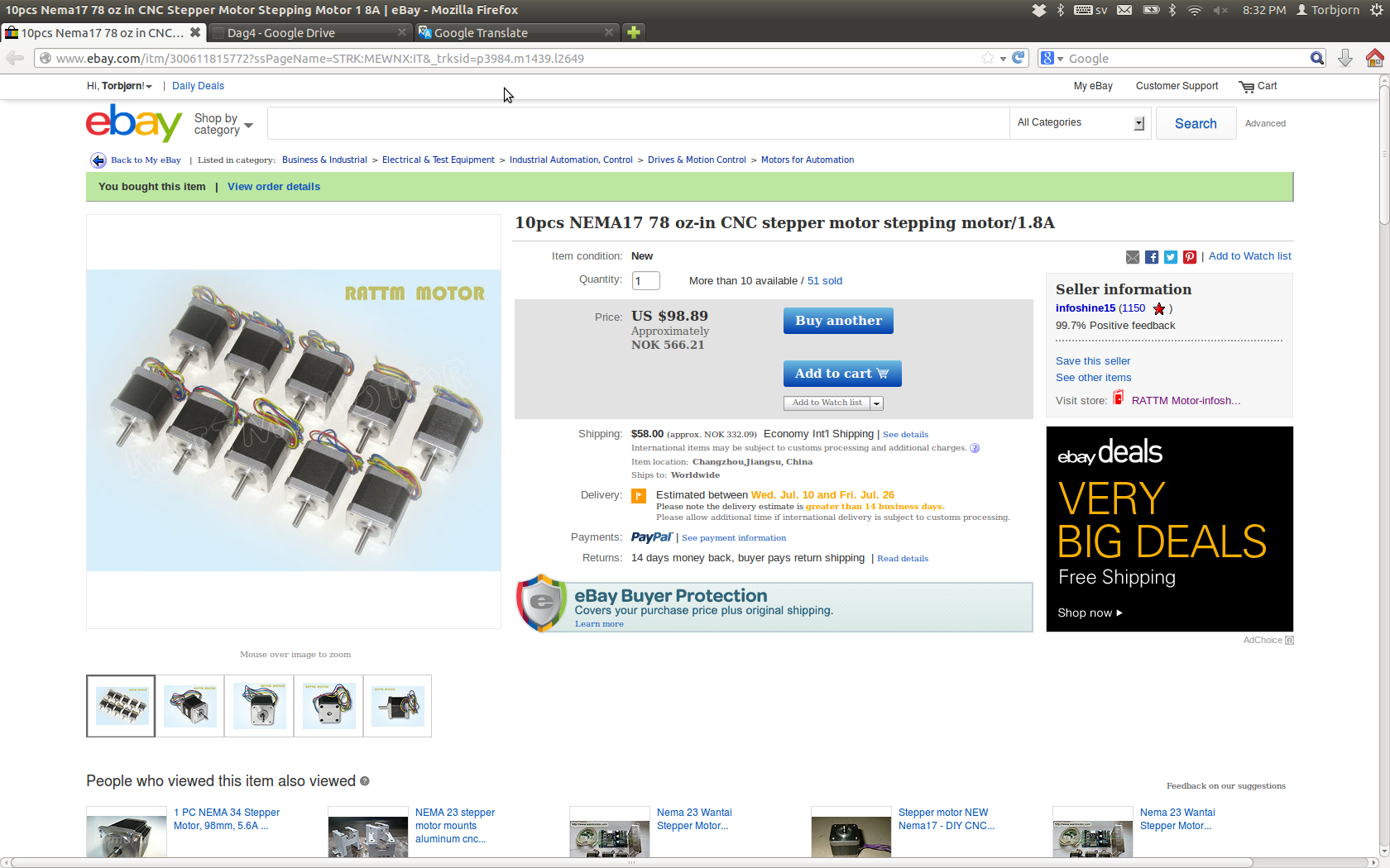
Since Larvik couldn't deliver all the small stuff I needed, I turned to good
old Ebay for belts, linear bearings, M2.5 screws, XLR-contacts and stepper motors:
The stepper motors I bought on Ebay. They had the model name
17HS8401 and a holding torque of 52 Ncm at a current of 1.8A. They were chosen
because the reprap.org wiki recommended at least 40 Ncm holding torque.
Sluggo helped by making a little
wiki
to store all the important specs (in Swedish).
- tobben
Torbjørn Ludvigsen
Today was a better shopping day. A local hardware store cut me the smooth rods
I needed for 25 NOK. "And that gives us huge margins", was the owners comment
on the price, so I guess smooth rods are really cheap when you buy in large
quantities. If I had a garage, I would try to do that.
Sourcing a Reprappro Mendel in Larvik. Day 2 and 3
29-1-2014
Bought a bunch of screws and searched the whole town for seven 623-bearings.
I only found three of them, and they were excessively expensive (nearly 100 NOK each!).
Screws of size M2.5 weren't available either.
Nobody in the hardware and electronics shops knew what an XLR-socket was, so I
ended up buying on of a wrong type. Linear bearings of the type LM8UU were also
impossible to find. One shop could order really expensive ones if I gave them
the exact measures, but I declined. Couldn't find smooth 8 mm rods either.
Conclusion:
The parts needed to build a Reprappro Mendel are not readily available nor
cheap in the city of Larvik.
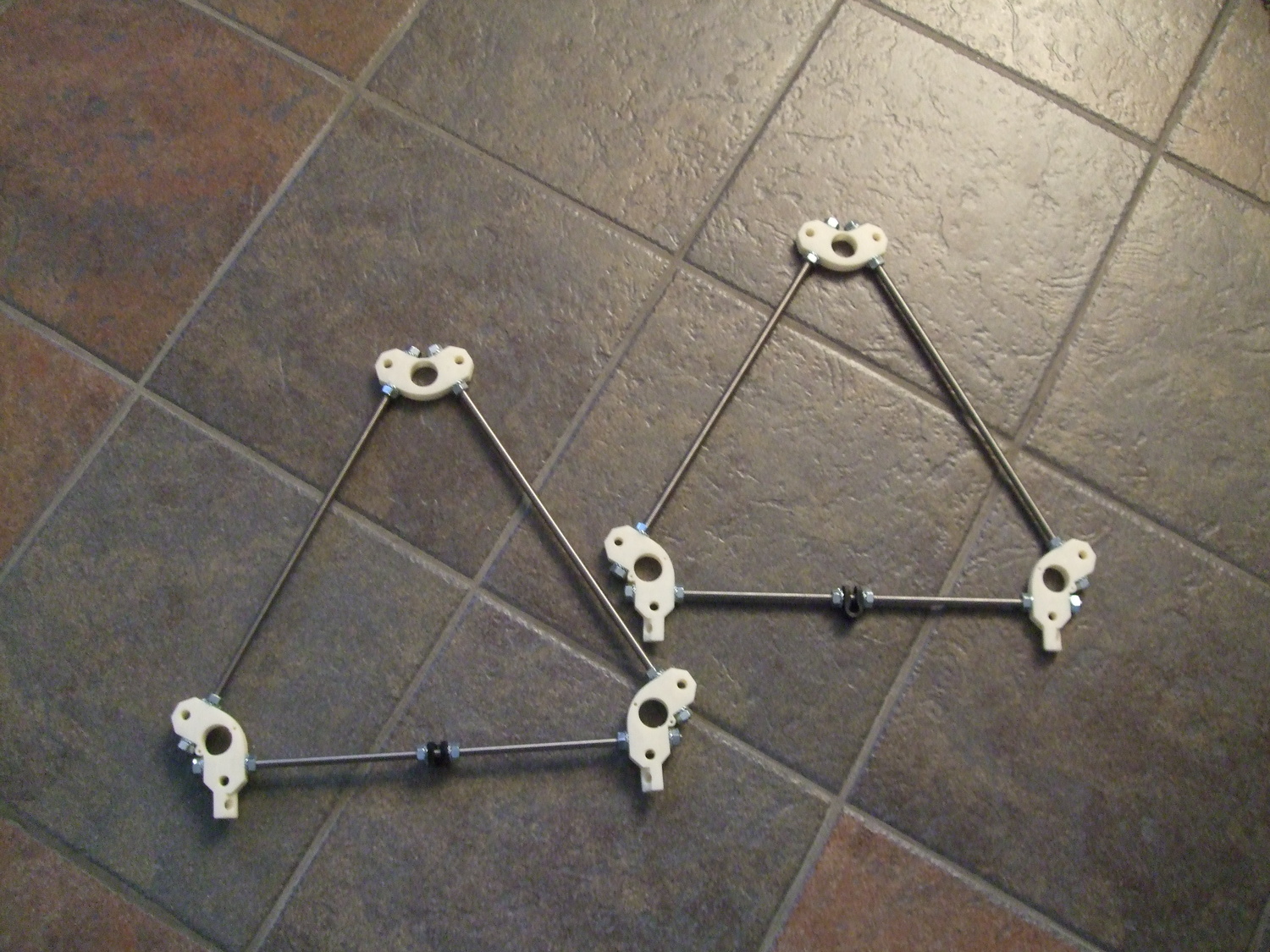
The first hardware actually mounted together, the end triangles of the frame.
Four of the printed parts split in half because of a weak layer
(had some problems with the extruder when I was printing them).
They were easily glued together with two-component epoxy though.
Enough hardship for today.
One thing actually went really well. I managed to involve Dad when mounting
together the skeleton:
The skeleton of what is going to be a Reprappro Mendel.
I think involving him in the build greatly increases the chances of him wanting
to test it when it's operational.
I also had a failed attempt to buy a Prusa Nozzle, which I would really like
to try out. They were sold out. It's nice to see business going well for
Reprap open hardware producers. There's lots of interesting hot ends out there,
but to save time and effort I decided to go for a standard Reprappro
hot end kit from Emakershop this time.
- tobben
Torbjørn Ludvigsen
Bought a bunch of screws and searched the whole town for seven 623-bearings.
I only found three of them, and they were excessively expensive (nearly 100 NOK each!).
Screws of size M2.5 weren't available either.
Nobody in the hardware and electronics shops knew what an XLR-socket was, so I
ended up buying on of a wrong type. Linear bearings of the type LM8UU were also
impossible to find. One shop could order really expensive ones if I gave them
the exact measures, but I declined. Couldn't find smooth 8 mm rods either.
Conclusion:
The parts needed to build a Reprappro Mendel are not readily available nor
cheap in the city of Larvik.
Sourcing a Reprappro Mendel in Larvik. Day 1
28-1-2014
Last summer holidays, I decided I wanted to build a Reprap to my parents to see how useful
it could be to them as non-computer-wizards with little experience of the idea of
3d-printing. To make it a little more interesting, I decided to use printed
parts from my Printrbot+, sigrid,
and to buy the vitamins one at a time, preferably in Larvik.
It would be a nice test of how available these Reprap parts really are (or of
how good Larvik is as a hardware shopping city...).
For BOM and all other information, I used
the build-instructions from reprappro.com.
I got to work immediately and ordered
a heatbed:
Ordering a very cheap heatbed on ebay.
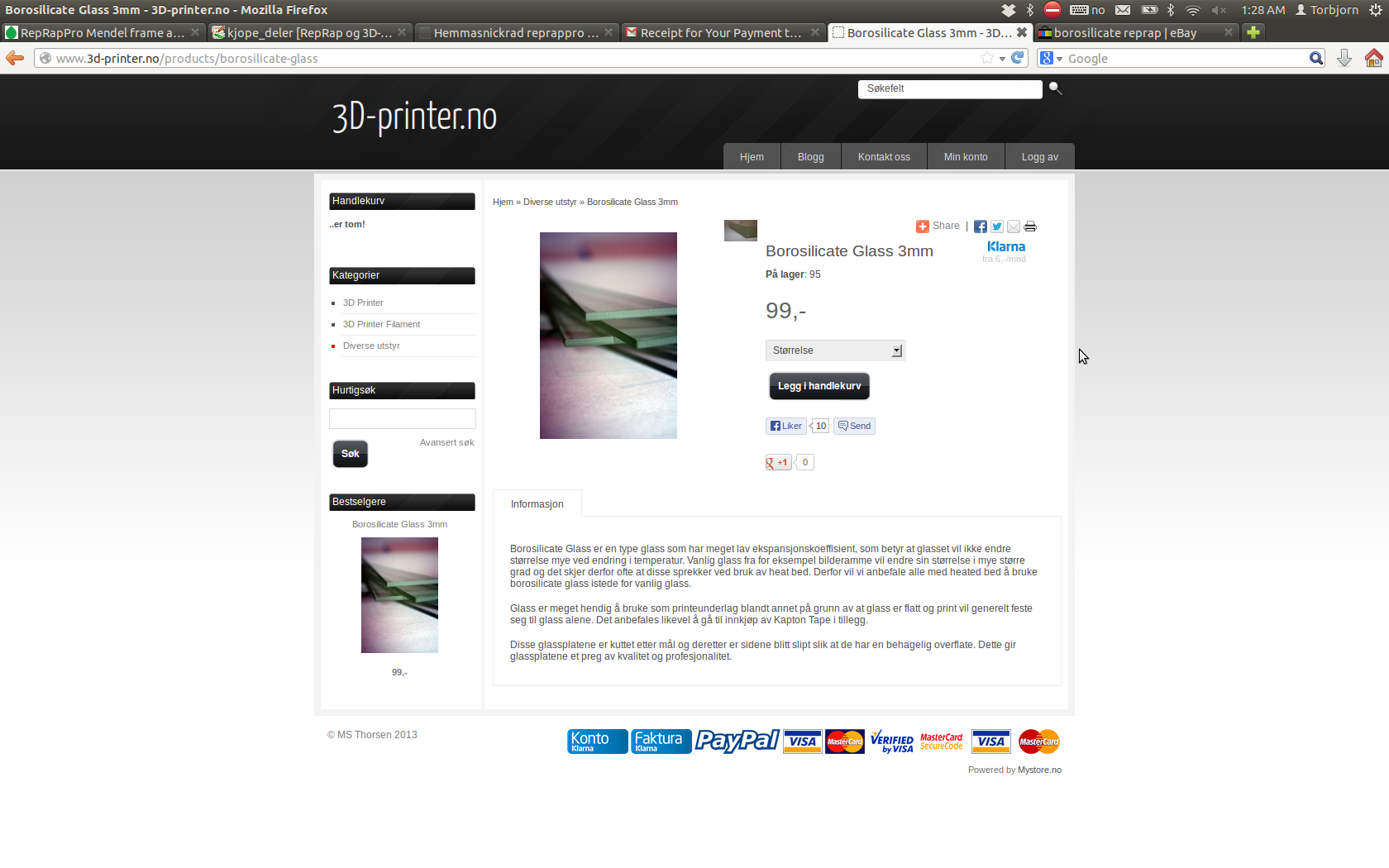
I also ordered a borosilicate (heat resistant glass) plate:
Ordering a borosilicate plate from 3d-printer.no.
All the M8 threaded rods + nuts were bought in the local hardware store Biltema
for 913 NOK. We could have saved 360 NOK by choosing galvanized steel instead
of stainless, but dad thinks stainless looks better. Cutting the right lengths
were done with dads grinder.
Cutting threaded M8 rods with a grinder. The rods are clamped with wood-blocks not to damage the threads.
- tobben
Torbjørn Ludvigsen
Last summer holidays, I decided I wanted to build a Reprap to my parents to see how useful
it could be to them as non-computer-wizards with little experience of the idea of
3d-printing. To make it a little more interesting, I decided to use printed
parts from my Printrbot+, sigrid,
and to buy the vitamins one at a time, preferably in Larvik.
It would be a nice test of how available these Reprap parts really are (or of
how good Larvik is as a hardware shopping city...).
For BOM and all other information, I used
the build-instructions from reprappro.com.
I got to work immediately and ordered
a heatbed:
Hello, World!
27-1-2014
Welcome, RepRappers!
I've spent a lot of time RepRapping over the past year, so I thought it was time
to make a blog about it. I'm planning to post at least once a week for at
least 10 weeks forward. The posts will mostly be condensed everyday tinkering,
but I have a hope that over time, I can use my knowledge from engineering physics studies
to make some actually useful contributions to the RepRap community.
Added 1-2-2014:
Great news! My friend sluggo will also be posting here from time to time.
I would say it radically improves
the chances of posts with actually useful contributions to the community appearing on this blog.
Welcome, sluggo!
Enjoy!
- tobben
Torbjørn Ludvigsen
Welcome, RepRappers!
I've spent a lot of time RepRapping over the past year, so I thought it was time
to make a blog about it. I'm planning to post at least once a week for at
least 10 weeks forward. The posts will mostly be condensed everyday tinkering,
but I have a hope that over time, I can use my knowledge from engineering physics studies
to make some actually useful contributions to the RepRap community.
Everything on this homepage, except those videos who are published via Vimeo or Youtube, is licensed under the Gnu Free Documentation License.
The videos published via Vimeo or Youtube are also licensed via Vimeo or Youtube.


