I recently decided to use three circuit boards in my Hangprinter v4 prototype: One
DuetWifi, and two
ODrives.
It turned out to be a challenge to get wiring and communication to work the way I wanted.
I wanted to use stock RepRapFirmware (RRF) on the DuetWifi, and stock ODrive Firmware (OF) on the ODrives.
No special "Hangprinter Firmware", only Hangprinter configuration of stock firmware.
I wanted to connect the two types of boards directly with jumper wires.
No special multiplexers, filters, level shifters or anything like that between the boards.
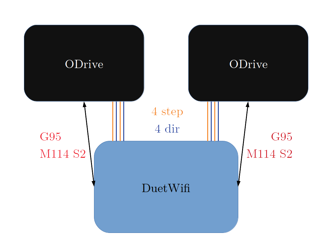
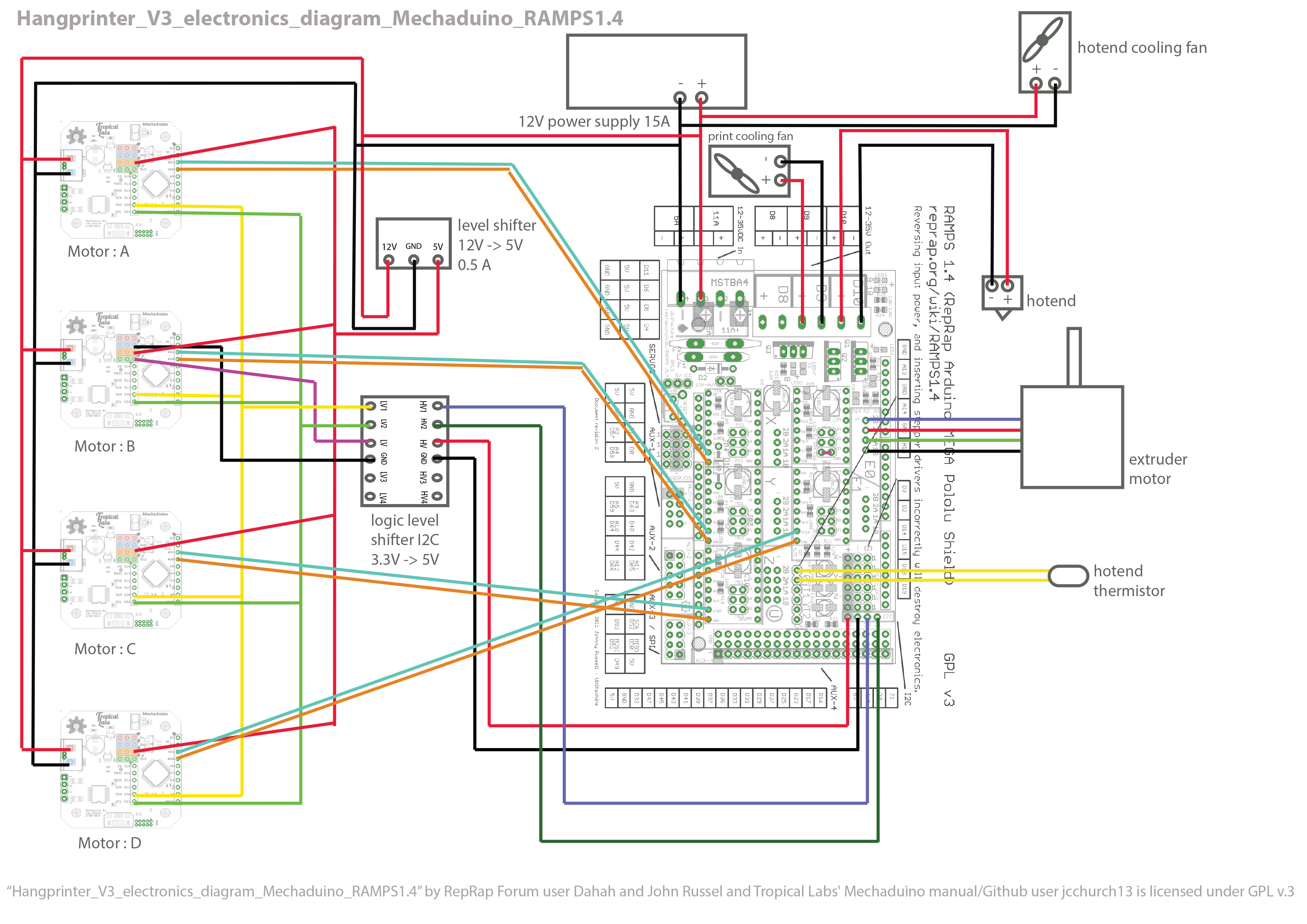
I aimed for something like this:
Diagram of wires and communication between DuetWifi and ODrive boards on HP4.
G95 and M114 S2 is the minimal set of gcodes
that must be supported to enable auto calibration.
Both these gcodes require signals (other than step/dir) to flow between the boards.
Why The Non-step/dir Wires?
Convenience.
Let's call them convenience wires.
The step/dir wires can only be used to communicate a desire for incremental movement.
Through convenience wires we can tell ODrives to more exciting things, like:
Live PID tuning
Live tuning of min/max speeds and currents
Live configuration of microstepping
Trajectory planning
Interfacing with yet more circuitry, like cameras and load cells
Anti-cogging
Torque estimations via motor current readings
Motor shaft position readings
Enable/disable position control, current control, or velocity control
We want to make ODrives do exciting things by talking gcode to the DuetWifi via wifi,
and have the DuetWifi forward commands to the ODrives via the convenience wires.
The first exciting thing I'll focus on implementing in HP4 is better auto-calibration.
Anchor positions and line buildup parameters should be calibrated during the same routine,
and the user should just have to start this routine and wait for it to finish.
Making Boards Talk About Exciting Things
The basic step/dir communication was straightforward to set up.
Both boards and firmwares had good support and documentation already.
So we got to feature parity with HP2 quickly.
Not super exciting, but a really nice start.
With no more than basic setup and a step/dir connection, the ODrives showed promise of
being able to make HP4 run really really fast.
The HP3 got beyond HP2 features by talking i2c protocol through convenience wires (and a level shifter).
Unfortunately, ODrives lack i2c support.
ODrives are only prepared for controller communication via their
universal asynchronous receiver-transmitter (UART).
To be more precise, ODrives have one pair of Tx/Rx pins with 3V3 logic levels,
talking RS-232 with 8-bit words, no parity bit, one stop bit, at a rate of 115200 bits per second.
So, I had to go for UART in the HP4 convenience wires.
There were two small problems to overcome:
ODrive Firmware did not support UART and step/dir to be enabled at the same time.
DuetWifi had only one pair of Tx/Rx pins exposed.
Madcowswe, ODrive's main dev, helped solve the first problem real quick.
Within a few hours, he added firmware support for step/dir and UART to be enabled simultaneously.
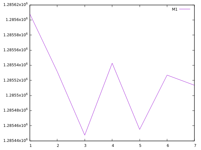
I carried out some basic tests of the step/dir communication.
Step control counts after moving the motors really fast back and forth for 24 seconds.
This test was run at a 70 kHz step rate, and shows ca 160 lost steps.
To avoid step loss, I recommend a step rate below 20 kHz.
This puts a (high) cap on speed versus resolution.
If you want a max speed of 2000 mm/s, then each step must result in at least 0.1 mm of movement.
Higher speeds are of course possible if we double check step counts
(or indeed send the movement commands themselves)
through the convenience wires.
Dc42, who is DuetWifi and RRF's main dev, helped me with the second problem.
He told me that one of the DuetWifi's pair of SPI pins were really USART pins,
and could be reconfigured in software to act as UART pins.
It took me a few days to get the pin re-configuration right, and stock RRF currently doesn't support it.
I will of course stay in touch with dc42 and try to get all HP4 functionality merged.
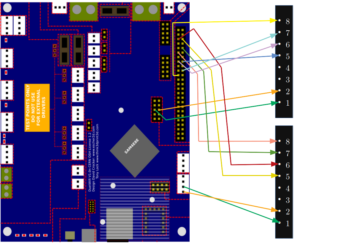
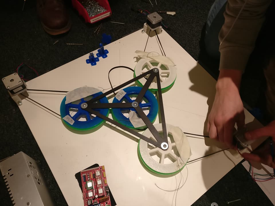
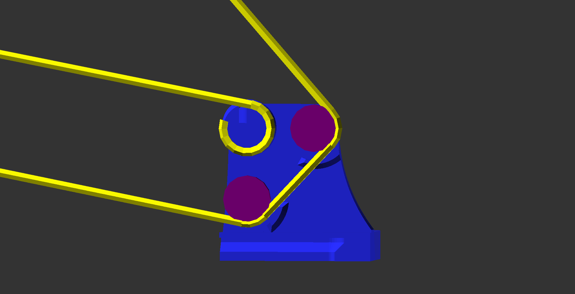
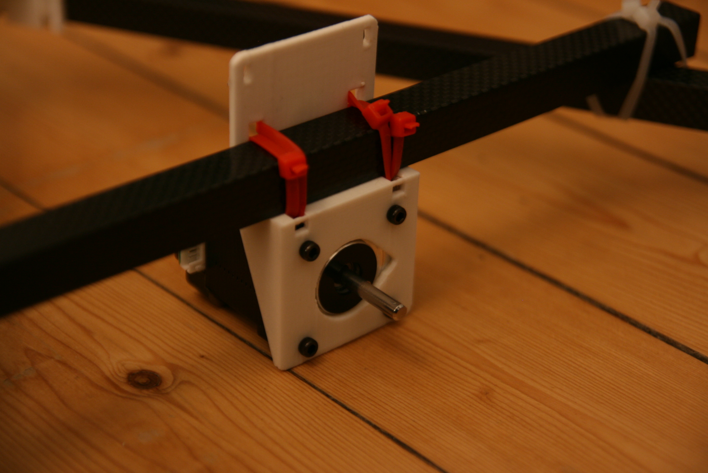
How To Connect And Configure HP4 Convenience Wires
There are 12 communication wires to be connected between the DuetWifi and the two ODrives:
... to both ODrive boards. Save and reboot as always after updating ODrive configuration.
The pin ordering on the ODrive side might seem a bit funny:
Pin 5: dir axis0
Pin 6: step axis0
Pin 7: step axis1
Pin 8: dir axis1
Explanation axis 1: We simply keep OF default assignments on pins 7 and 8.
Explanation axis 0: Pin 5 does not have the low pass filter needed for step signal transmission,
only GPIO pins 1, 2, 6, 7, and 8 have such a filter behind them
on the ODrive v3.5.
I'm still a bit unsure whether dir signal on the non-filtered pin 5 will work well in the long run.
An oscilloscope would be needed to really see if the dir signal quality is good enough.
The small tests I've conducted by just counting steps with the encoder have shown no dir errors thus far.
The following gcodes will enable right UART pins on the DuetWifi:
M569 Q0:1:115200  ; Connect ODrive 0 to Serial device 1 at 115200 baud
M569 Q1:99:115200 ; Connect ODrive 1 to Serial device 99 at 115200 baud
... and the following gcodes maps step/dir signals to the right pins on the DuetWifi:
M669 K6                 ; This is a Hangprinter
M584 A5 B6 C7 D8 P4     ; map ABCD-axes to ext driver pins (four visible)
- tobben
Torbjørn Ludvigsen
I recently decided to use three circuit boards in my Hangprinter v4 prototype: One
DuetWifi, and two
ODrives.
It turned out to be a challenge to get wiring and communication to work the way I wanted.
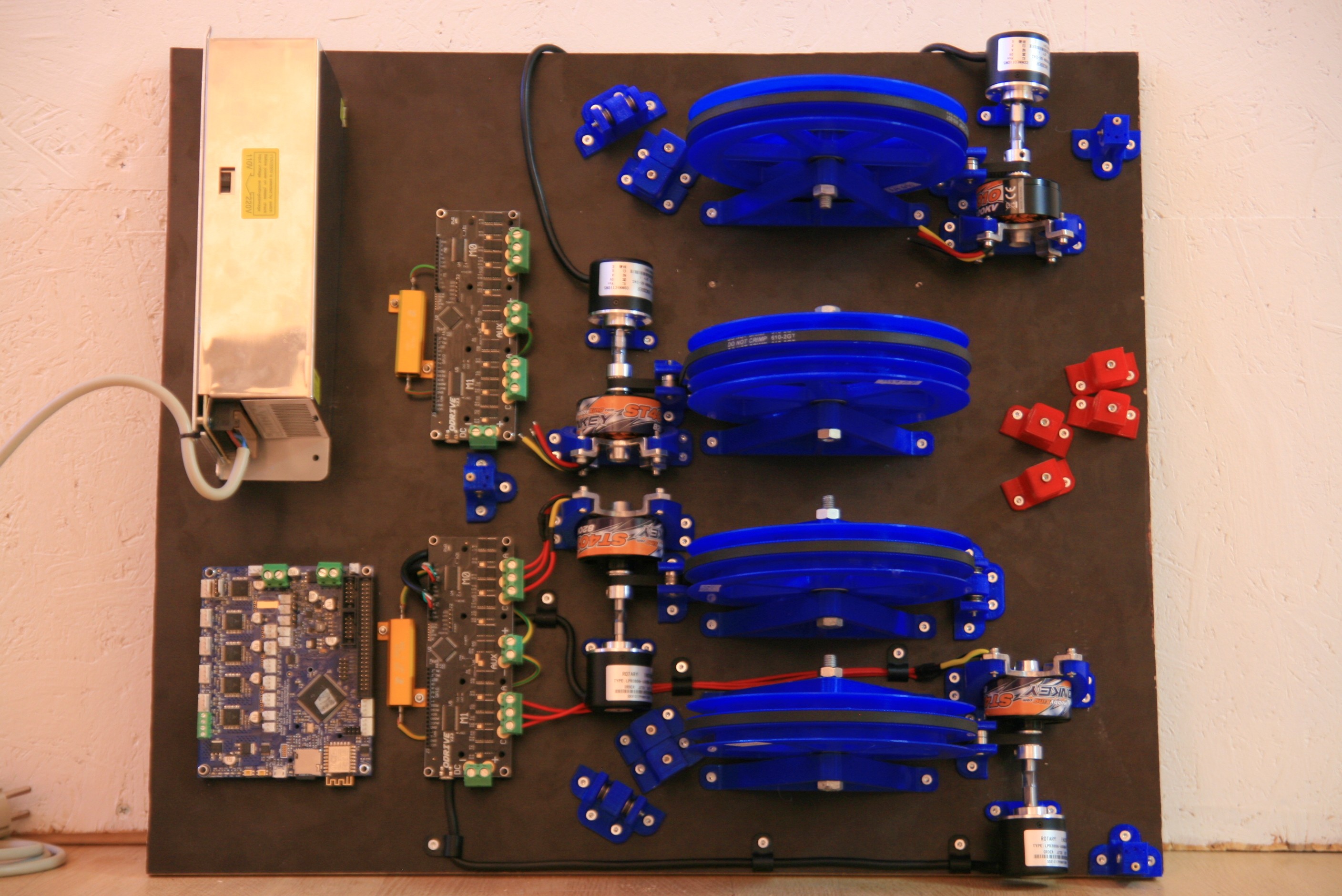
Office And HP4 Prototype One
17-10-2018
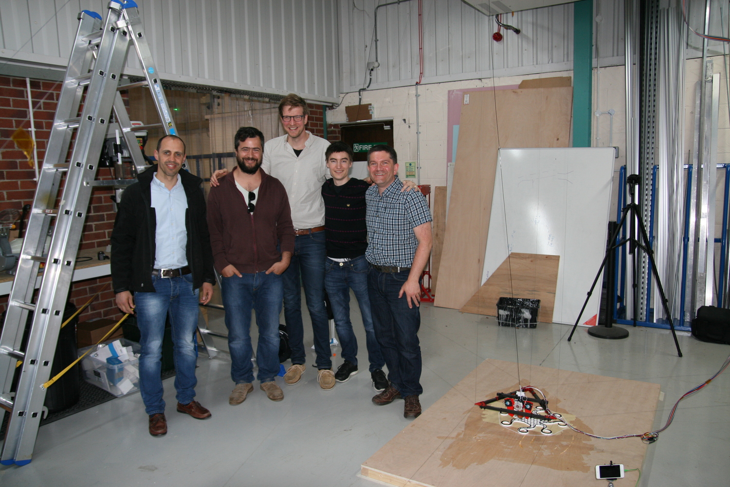
I recently got my own dedicated Hangprinter space.
It is a room in an old industrial building, in a collective of potters and musicians.
Well, it wasn't really a room when I first got it. We built a wall, and made it a room.
To the right in pic below.
It's within walking distance from my home, has home made coffee cups in the kitchen, two massive kilns at the entrance,
and good live music every single evening.
It's a messy, friendly, and beautiful place.
I feel free here.
If you look closely at the picture you'll notice my little Mendel and its latest offspring;
the latest HP4 prototype.
I've been working on it quite intensely since I got my new space.
Check out the version_4_dev branch if you want the source.
Here's a quick overview:
HP4 Prototype One
This hardware prototype is made to allow faster, stronger, smoother, more accurate motion.
The first three goals motivate choices like
BLDC motors driven by oDrive PCBs
DuetWifi main PCB
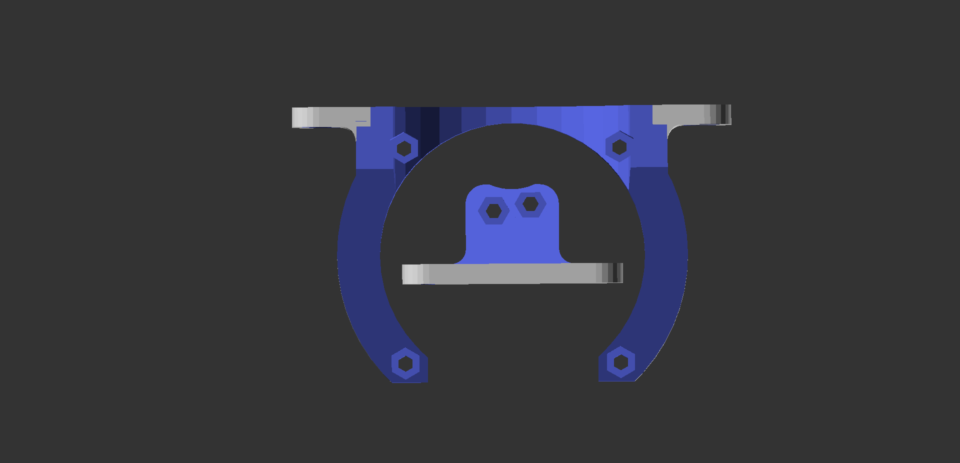
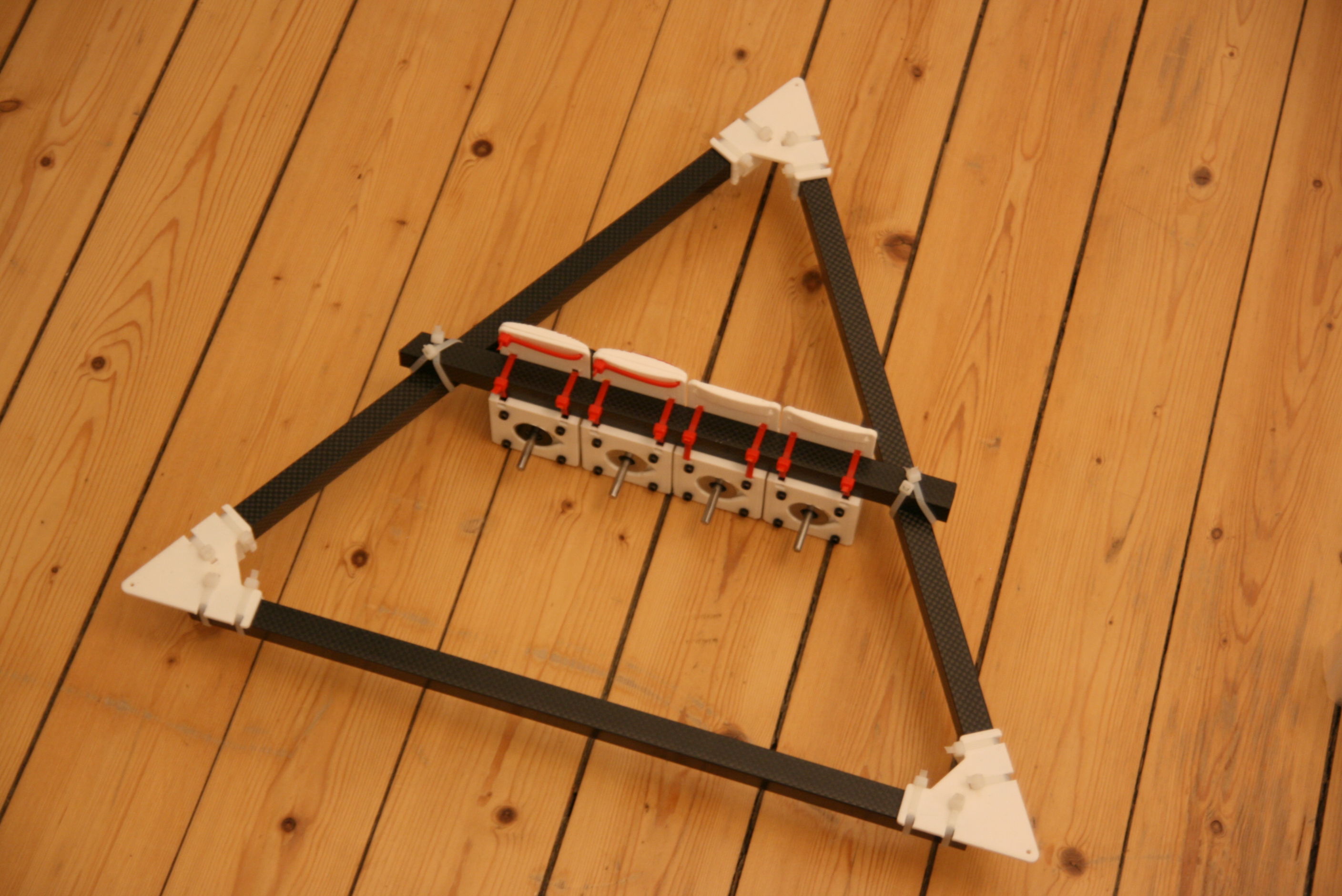
All ABCD axes are geared down with pulleys
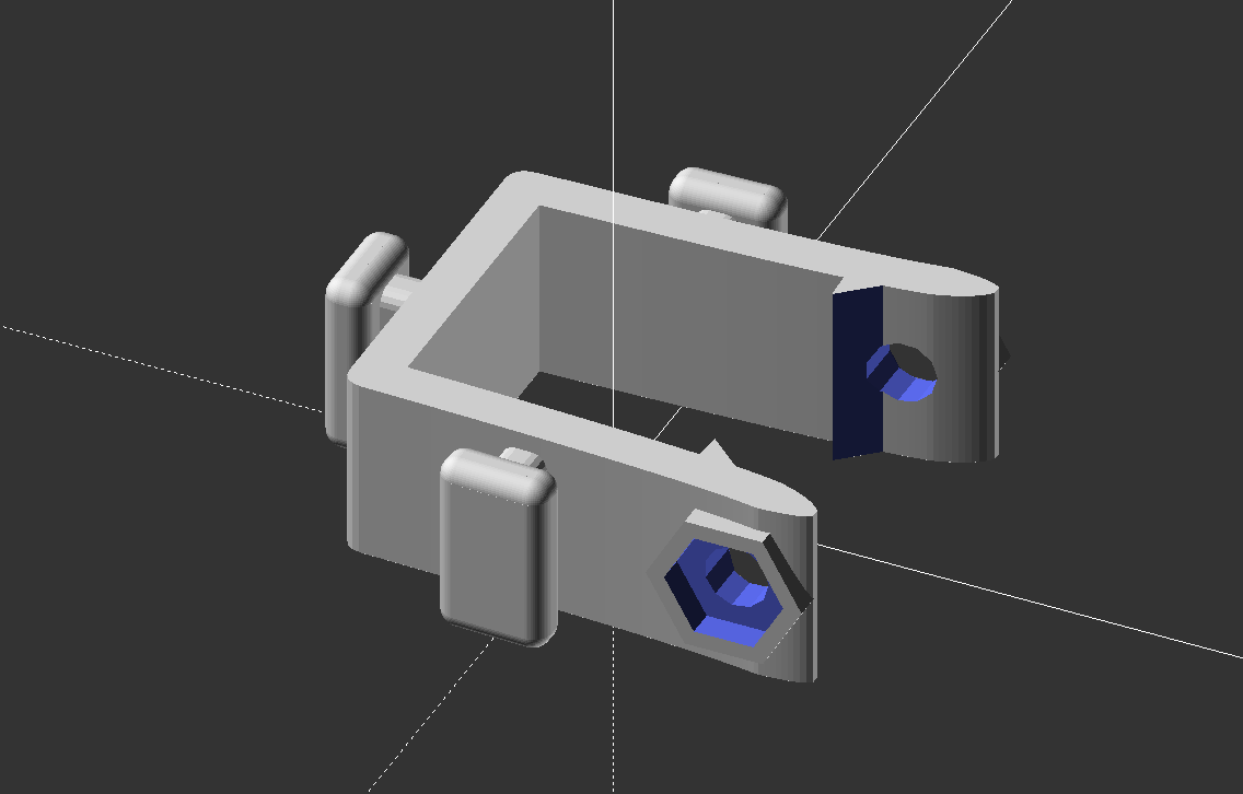
Corner clamps with all axes geared down. Sewing machine wire guide spares used to keep D-lines in place.
Gearing down the D-axis enables us to use high speed BLDC motors, and will allow us to lift heavier tool heads in
the future.
To really get more accurate, we need better calibration, which motivates
Belt driven spools
Larger spools
More spools (one for each line)
Other hardware changes are made just for looks and tidy order:
Spools are raised upright
Lines are routed via idler pulleys internally on the ceiling unit
All parts along the line paths have been beefed up to make them more sturdy since
powerful motors and small plastic parts must live together in harmony.
This scares me a little.
Previous anchor line rollers could break if you stepped on or kicked them by accident.
The new ones are much more likely to survive such treatment.
HP4 Prototype One - Not As Finished As It Looks
(At least better than the first HP3 prototype's slogan: might be awesome if it works.)
Those hardware changes are all fine and dandy, but the more important improvements require better software, which is
not yet written.
The more important improvements include
Flex compensation
Better calibration
Automatic homing
Without them, we can't ave adequate accuracy, except close to the origin.
I mean, you can make 1 m movements (video),
but you can't print a decent Benchy out there.
Flex Compensation
Flex is an obvious pain point in the HP3 since its firmware assumes nothing flexes, while in reality everything flexes.
In extreme positions, this can give errors at the order of centimeters.
I mentioned earlier that all axes are geared down with pulleys on the HP4 prototype.
This means twice as much line between anchors and effector, and hence only half the flex.
Sturdier plastic parts also helps.
The real fix however, is to measure flex and compensate for it in firmware.
The equations have been worked on in an earlier post,
and the HP4 should definitely use them when planning its every move.
Better Calibration
There's actually a conceptual error in the current semi-automatic calibration routine
(apart from the truncation error that was found and fixed).
The M114 S1 command outputs line lengths.
It gets these line lengths by reading motor shaft position and compensating for line buildup.
But line buildup compensation requires correct anchor calibration in order to work correctly.
So the data is imperfect even if the user does a perfect job while collecting it.
The obvious way to fix this is to have M114 S1 output shaft positions,
and do the line buildup compensation within the cost function instead.
And once we've moved buildup compensation into the auto-calibration code, then we have the chance to throw the buildup
factor in there too.
The buildup factor is a measure of how much volume a meter of line takes up.
This has been guesstimated based on line diameter up until now, and it's been known that the guesstimate is imperfect, which makes the whole buildup compensation even more
imperfect than it could be.
Hopefully, the improvements described above would allow us to auto calibrate by moving the nozzle to known positions.
Such calibration would give more accurate result than the current random-position-based method.
We tried it with the HP3, but it failed.
I think it failed because errors from flex, truncation, and imperfect buildup compensation were too big for the optimization
algorithms to work with.
Automatic Homing
Perhaps the most obvious accuracy bottleneck in HP3 stems from the manual homing.
Human hands are great precision tools, but not good enough for 3d printing.
Three things vary between manual homing procedures.
The actual home position of the nozzle.
The tightness of the lines in that position.
The flex or loose line that has accidentally gotten wound onto the spools.
A good, cheap, and simple homing routine would be to crash (with a repeatable force) the effector into a bracket in
the ceiling,
and then tighten ABC-lines to a repeatable tension, before moving down to the origin in a controlled fashion.
We have previously been prevented from doing that long moves in a controlled fashion.
This was due to inaccurate calibration parameters, both for the anchor positions and the buildup compensation.
It's funny how bad accuracy leads to worse accuracy and vice versa.
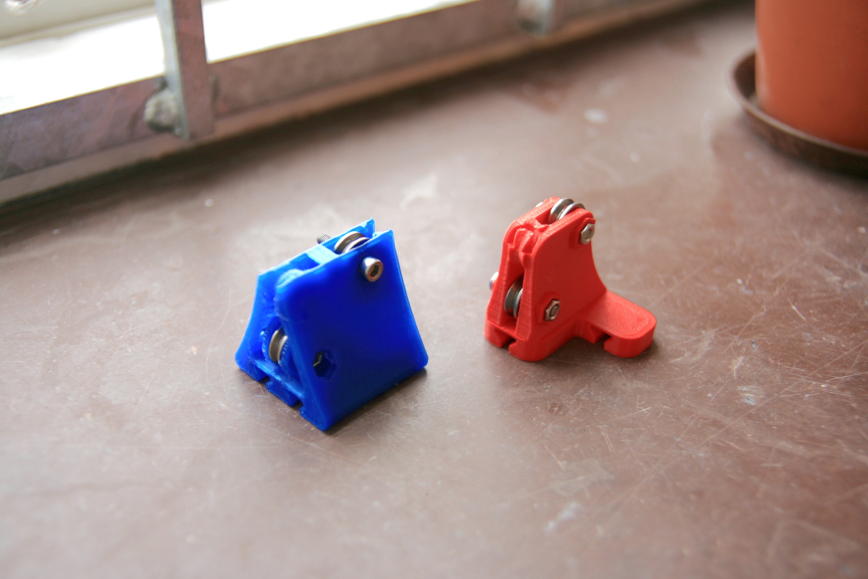
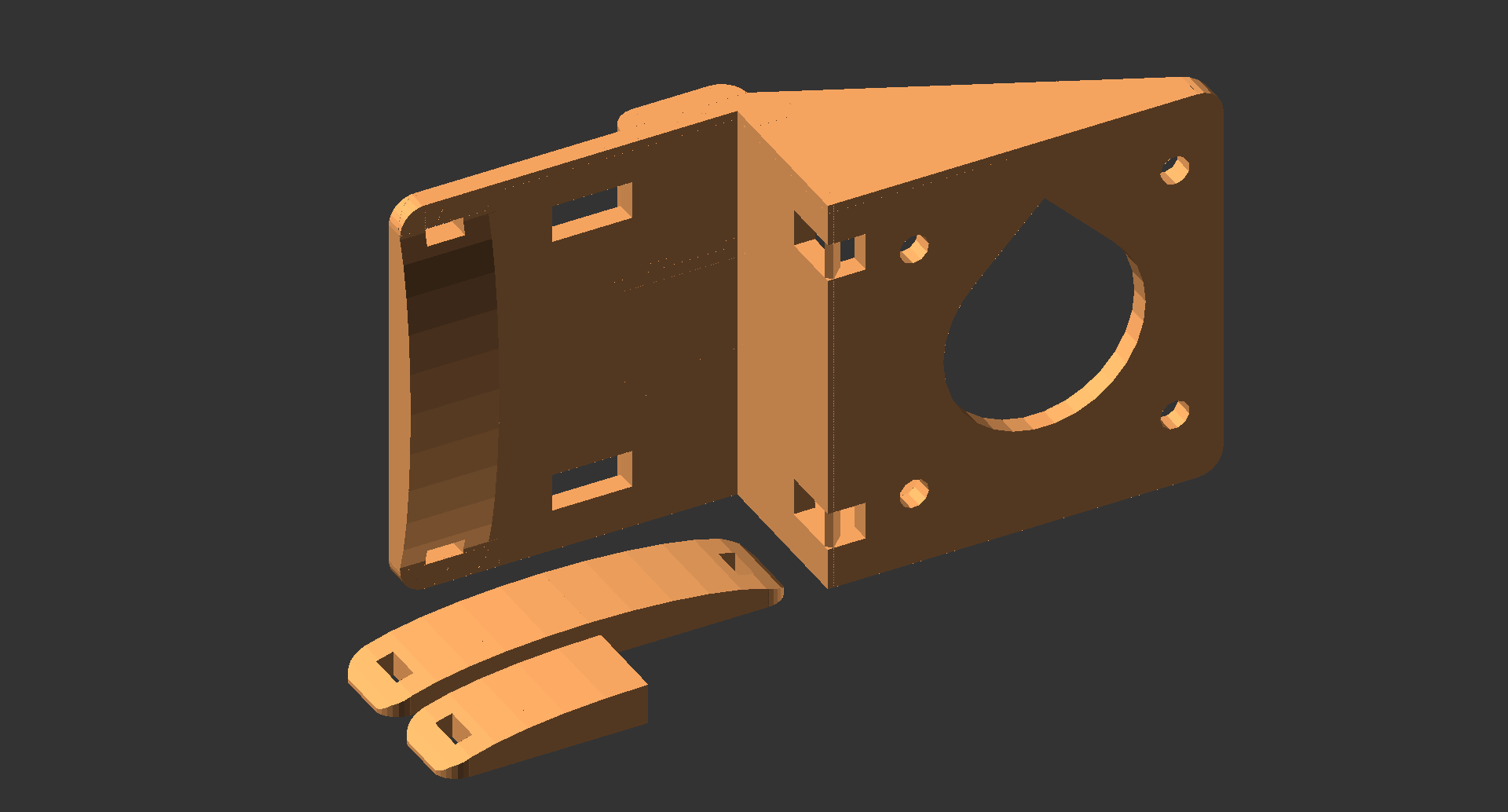
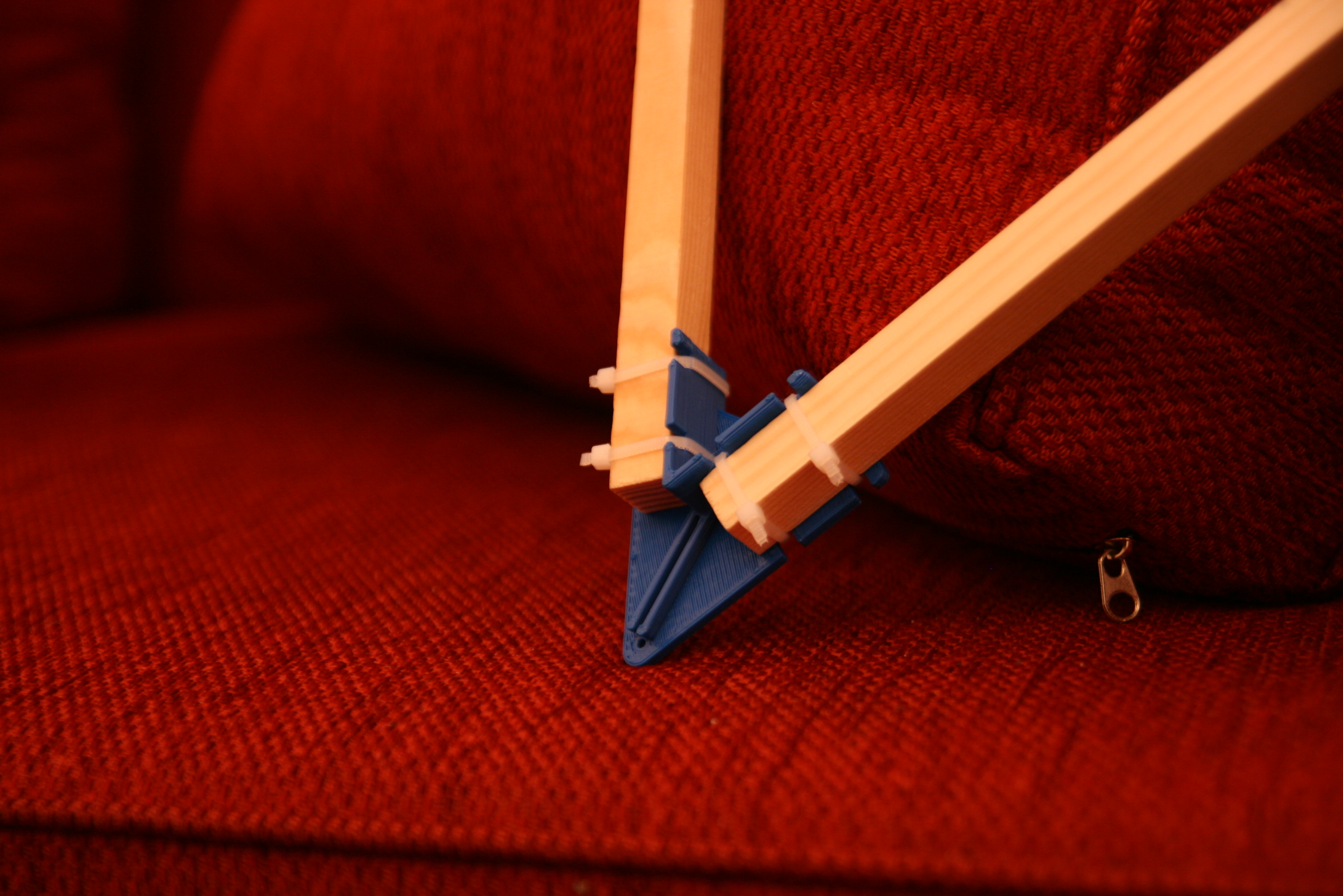
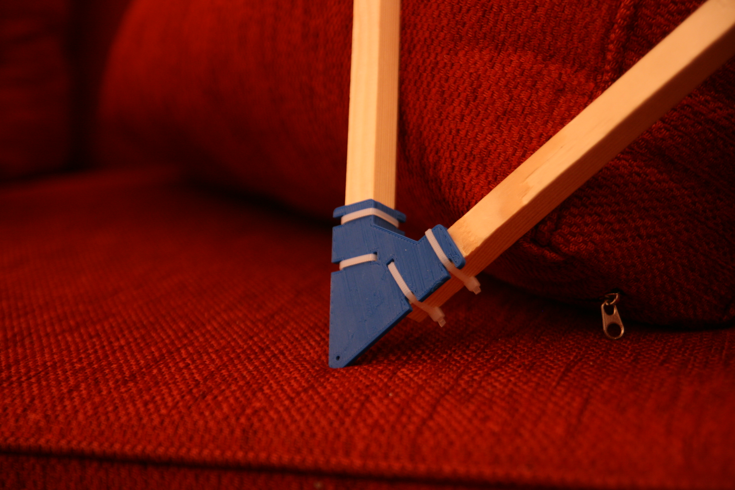
The brackets I use to mount the BLDC motor
and the encoders with their oddly offset mounting holes.
Epilogue
And, well, that's only the beginning of the prototype's overwhelming unfinishedness.
Will the belts stay on, or will they jump off? Will they wear out quickly? I don't know.
Iterate and iterate again. The line must never fall off that bearing.
I'm still unsure if the extensive use of vgroove bearings is wise, or if the lines will occasionally fall off.
My unstructured testing has convinced me to at least try and trust the 44 line guiding bearings in this prototype.
I've only been able to make lines fall off bearings by pushing hard with needles and the tip of a knife.
But you know, I fear Murphy's law will come and bite me.
Time will show.
I'm also unsure if the BLDCs will give satisfactory stiffness and smoothness at the same time.
I'm planning to use the experimental anti-cogging feature
to make the motors move really smoothly like expensive BLDCs with tilted magnets do.
Last, but not least, will the world make fun of my line_verticalizer because it looks like a fish?
Only the brave gets to learn interesting stuff the hard way.
- tobben
Torbjørn Ludvigsen
I recently got my own dedicated Hangprinter space.
It is a room in an old industrial building, in a collective of potters and musicians.
Well, it wasn't really a room when I first got it. We built a wall, and made it a room.
To the right in pic below.
Crashdummies Wanted
9-7-2018
The Hangprinter support in RepRapFirmware is looking for pre-alpha testers!
You can be the first person to combine Hangprinter with Duet, RepRapFirmware, and 32-bit controllers.
If you get it working, your Hangprinter will be the fastest one on earth.
You will be on the bleeding edge, and help Hangprinter development.
See the previous blog post and
duet3d.com for more on how Duet and RepRapFirmware will make HP4 better than HP3.
Wiring
I don't have a Duet specific wiring diagram.
You will have to compare with two other diagrams:
Compared to Duet's default wiring,
you will wire the ABCD (Mechaduino) motors differently.
You will not connect endstops or bed heater, but you will connect i2c cables.
Compared how the RAMPS is wired in the HP3 manual (click for larger):
The Duet doesn't need the logic level shifter.
The Duet's i2c pins are marked TWD0 and TWC0 on the silkscreen.
The Mechaduino A's pin D0 connect to the E2_dir pin on the Duet (see silkcreen).
The Mechaduino A's pin D1 connect to the E2_step pin on the Duet.
B connect to E3, C connect to E4, D connect to E5.
The Duet can handle 24V power, which will make your motors perform better.
Then go on to learn about the changes I've made in the pull request,
here.
I've built a Duet2_RTOS binary that you can upload directly.
It is found
here.
If you're experiencing RTOS related bugs, you could try the non-RTOS build.
Binary
here.
After the dozuki-guide was written, I've added spool buildup compensation, and support for ABCD-parameters to the gcodes
M589, M92, M201, M906, M203, M208, M350, and M566.
I've also added support for torque mode (G95) and gcodes needed for auto calibration (G96 and M114 S1).
Here are some gcodes I would use to set up my RepRapFirmware for use with Hangprinter and a DuetWifi:
M669 K6 ; Set Hangprinter Kinematics
M669 Aax:ay:az Bbx:by:bz Ccx:cy:cz Ddz ; Set anchor positions
M584 A5 B6 C7 D8 P4 ; The step/dir of Mechaduinos connect to exp E2 E3 E4 E5
M584 E0:1:2:3:4 ; Regard all TMC2660s as extruder motor drivers
M569 P5 I0x0a ; The Mechaduino connected to driver 5 (E2_step/dir) ...
M569 P6 I0x0b ; ...  is connected to i2c and has address 0x0a
M569 P7 I0x0c ; ditto for BCD.
M569 P8 I0x0d
If you have configured Marlin for a Hangprinter before, you notice that many settings are missing in the above.
Right now, the M669, after first getting K6 configured, will also accept parameters
Q, W, R, U, O, G, H, J.
These are, however, likely to change and only used for fine tuning anyways, so I don't want to document them here.
Should you need to use these parameters, see
the lines where they are parsed in the source code.
Sending a M669 with no arguments will print settings, which will also give you hints.
This DuetWifi will get connected to its Hangprinter parts in August.
Since this is open source hardware, and I'm going on holidays, I invite you to get ahead of me =)
Mechaduino Firmware
The Mechaduino firmware found here
should make your Mechaduinos respond to RepRapFirmware's G95 and G96 calls.
Getting Help
This month (July 2018) I will take my first ever holiday from the Hangprinter Project.
Me and my wife will seek family roots in the northernmost parts of Norway.
This means I won't check the forums as often as usual, if at all.
RepRapFirmware Related Questions
I'm sure the RepRapFirmware maintainer dc42, and the general community of Duet/RepRapFirmware users, will do their best
to help if you ask good questions.
Reading the Duet documentation and information in
the pull request itself will help you ask good questions.
The dev branch that I'm making the pull request from is found here.
Remember that no RepRapFirmware users have previous experience with the Hangprinter.
Hangprinter Related Questions
Both the forum thread and the Facebook group
reach people who are knowledgeable about Hangprinter.
They are eager to help and to see you succeed. If you haven't already, give them a chance and ask a question =)
- tobben
Torbjørn Ludvigsen
The Hangprinter support in RepRapFirmware is looking for pre-alpha testers!
You can be the first person to combine Hangprinter with Duet, RepRapFirmware, and 32-bit controllers.
If you get it working, your Hangprinter will be the fastest one on earth.
You will be on the bleeding edge, and help Hangprinter development.
See the previous blog post and
duet3d.com for more on how Duet and RepRapFirmware will make HP4 better than HP3.
Design Goals and Electronics
1-7-2018
For Hangprinter v4, I'm changing out the design goals, and hence also the electronics and the firmware.
TL;DR: I'm going for DuetWifi and RepRapFirmware.
To talk meaningfully about design goals, I feel like I must first give you some:
Hangprinter Design Goal History
Hangprinter v0 (aka Slideprinter), was built just to investigate if lines on spools could be a feasible way forwards.
October 27, 2014.
The initial goal of the v1 design was simply to prove the Hangprinter concept.
I was not convinced that it would work at all, so it didn't make sense to talk about design goals beyond proof-of-concept.
However, reading between the lines of the potential rewards that I listed in a forum thread at the time,
one can get some hints about what I hoped for:
The most compact, easily printed, easily installed and easily distributed RepRap out there
Possibility to retract its strings and park close to the ceiling when not in use. Could make it popular where indoor area
is scarce
Extreme print heights (> 1 m)
The concept worked, and the v1 and v2 designs fulfilled the hopes in the above list (except the one about becoming popular
where indoor area is scarce).
The above picture was taken at the recording of a campaign video.
The subtitle of the campaign was (and still is) a design goal
Print big at low cost
Many Reprappers embraced the Hangprinter concept, but failed to complete their first Hangprinter build.
In a blog post in January 2017, I wrote in a blog post:
"It's made to be useful, so it also needs to spread."
A new design goal got very relevant:
Ease of build
Making builders succeed with assembly overshadowed all other design concerns for a while.
In March 2017, Alexander Osika (above) suggested a dual-unit Hangprinter, with the motors in the ceiling.
This would allow us to lay the spools out in a two-dimensional pattern,
and could be made straightforward to put together.
I also knew that new challenges would face us once ease of assembly got figured out.
The v1 and v2 machines had been hard to calibrate, and quite unreliable,
so in April 2017 I stated some new design goals in a blog post:
Closed-loop control
Automatic calibration
Even before achieving those goals, we started getting way better prints out with the dual-unit than we ever got with the
v1 and v2s.
Here from December 2017:
By the end of 2017 I iterated on this blog that I wanted Hangprinter to be spread and be useful.
The goal of usefulness motivated some compromising.
Auto calibration and closed-loop control were made possible with Mechaduinos,
who also made the build harder.
Below is an experimental single unit prototype using Mechaduinos.
It was never made standard because it was very hard to assemble.
The Mechaduinos are also very expensive.
Up until this point, I had stuck to cheap parts because both myself and most builders I've met wanted to keep investments
low.
Keeping parts cheap had helped the design spread, but using cheap components was not a goal in itself.
This might seem contradictory to the goal of low cost stated above, but cost must be compared to that of other large scale
3d-printers, ie thousands of dollars per print.
Cost must also take raw materials and percentage of failed prints into account.
With (human assisted) auto calibration in place, the dual-unit design with Mechaduinos was ready to spread through assembly
workshops.
Below is a picture from the very first hangprinter assembly workshop in May 2018.
Version 4
The Mechaduinos with their powerful processors and "smartness" also gave a glimpse of a machine I'd really like to own and use.
There is a new local design optimum down that road, one I hope we will call HP4 or HP5.
Version 4 will not seek to prove a minimal investment concept anymore.
The new design goals on the block are
A reliable workhorse
that people will enjoy using
and spreading
for profit
HP4 assembly workshops will still be a thing, but they will contain less wiring, more automation, and be even more expensive
than the HP3 workshops were.
The prospect of better prints and reliability will hopefully still make it worthwhile.
I would like the Hangprinter community to grow into a collection of people collaborating on a machine they use professionally.
More on economical aspects in the Bountysource
April 2018 update.
Since Hangprinters will often run over night close to where people live and sleep,
there's also a smaller and more specific new design goal:
Silent operation
Meeting this goal requires using nice extruder motor drivers, nice fans, and swapping out the big gears for belt driven
spools.
Towards The Universal Manufacturing Machine!
There's also a social goal in the Hangprinter Project.
As I see it, robots are rising towards becoming the dominant power factor in society.
I think it's important that the people owns the robots who fill their needs.
Giving away and selling robots is easy, but having it fill peoples needs is hard.
I think the best strategy for getting us there in the long run will
involve gearing Hangprinter (and indeed other designs) towards:
Becoming a Universal Manufacturing Machine (UMM)
This UMM should do the same to manufacturing as the CPU did to computing.
It doesn't have to solve all tasks fast, but it should solve a wide set of general tasks,
and it should be spread far and wide like infrastructure.
Whenever you want a physical object produced,
you should be able to tell a universal manufacturing machine to do it.
With craftsmanship and quirks coded in,
designers should be free to solve problems on a higher level of abstraction.
Needless to say, the software part of the Hangprinter Project will grow with time.
Experiments Underway And To Come
To create the version 4, we'll aim for:
Better main board electronics and firmware.
Belt drive: This will make axes smoother, which will improve the auto-calibration. The belt drive will also be faster to print, easier
to build and more quiet in operation.
Line flex compensation: This will improve accuracy and build volume much in the same ways as buildup compensation did.
Ceiling Landing Bracket: Both the ability to home by clamping towards it, and the ability to stay up when unpowered will improve the user experience.
Getting on towards the UMM from there will involve:
Tool changing: What E3D develops right now will be useful and relatively straightforward to implement on Hangprinter.
Particularly a super fast coarse infill tool is important for making HP practical and useful.
Computer vision: Both for auto-calibration, sanity checks, run time compensation, and dimensional guarantees.
Load Cells Along Lines: This will make the auto-calibration and line flex compensation better, which gives better print quality.
Multi-unit: Independent winch units communicating wirelessly.
A belt driven prototype by Alexander Osika.
Some of the listed experiments have already been started by myself and others.
Today I want to dive into the first one:
HP4 Electronics and Firmware
I won't try to give rigorous reasoning, because the parameters are so many.
Instead, I will give a vague list of priorities and share my limited knowledge and experiences.
Priorities. Ish.
Open Source Hardware.
Firmware we can incorporate into HP repo, preferably GPL.
More processing power (at least 4x Atmega2650).
At least 4 pairs of exposed, driver-less step/dir pins for connecting Mechaduinos.
Exposed 3V3 serial pins for connecting Mechaduinos.
A web interface.
Reasonable price.
24V input.
No streaming of gcode over serial USB, because of stuttering.
Willingness to incorporate Hangprinter software changes upstream.
Enough processing power to do on-board auto-calibration and line flex compensation.
Likely to support tool changing.
Lots of motor outputs and GPIO for tool heads.
Be compatible with cheap 32-bit hardware (Due+RADDS).
Do computer vision processing on-board.
Candidates
RAMPS+Marlin+Octopi
Most HPs in operation have this solution.
Builders add the optional Octopi for its web interface.
Stuttering from serial gcode transmission has been annoying on some prints, but bearable on new Pi hardware.
The top speed limitation caused by RAMPS (Atmega2650) being slow is also annoying, but has been bearable in the pre-SuperVolcano
era, since melt rates have limited print speeds anyways.
The required 5V->3V3 level shifting on the i2c serial pins has been an issue.
Failure to get the level shifting right on first try has caused burned boards and lots of debugging.
BeagleBone Black Wifi+Replicape+Redeem
This is by far the solution with the most processing power.
It might be the only commercially available 3d-printer solution that can realistically do onboard computer vision processing.
This solution doesn't have the four exposed step/dir pins we need to connect our Mechaduinos.
There have been some signals from lead dev Elias Bakken that we might get our pins in future versions of his new board
Revolve :)
Smoothieboard+Smoothieware
As far as I know, the Smoothieboard also lack the extension pins we need to hook in the Mechaduinos.
If I'm wrong, or if you know how to get the servos in there in another way, go for it and show us how!
I honestly have too little knowledge about this platform.
RADDS+Marlin
This was our first idea for HP4, and it is a strong candidate simply because it's the cheapest viable 32-bit option.
It requires very little programming to HP3's firmware onto a RADDS board.
However, Marlin devs are worried that merging Hangprinter support upstream will disturb their work flow.
See pull request here.
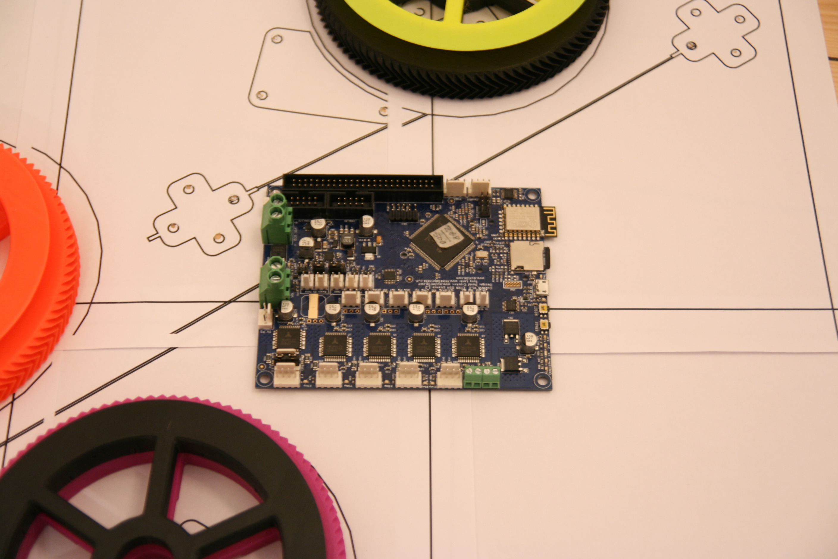
DuetWifi+RepRapFirmware
This is the solution I'm currently developing for.
It ticks all the boxes.
The well written RepRapFirmware, the great support, and all the available extension pins are really killer features.
See my RepRapFirmware fork here,
and my first substantial pull request here.
RepRapFirmware, despite being most often used with DuetWifi, also has support for RADDS, so users who prefer the cheaper
RADDS are not left in the dark here ;)
- tobben
Torbjørn Ludvigsen
For Hangprinter v4, I'm changing out the design goals, and hence also the electronics and the firmware.
TL;DR: I'm going for DuetWifi and RepRapFirmware.
Double Lines, Double Speed
8-6-2018
I got the chance to test out E3D's coming Super Volcano hot end recently.
The high melt rate let me try to print really fast for the very first time.
At first, I just upped the speed, and it looked like this:
During the longer travel moves in this video, the lines got very slack/over tight.
This is because the computations that translate between linear (cartesian) and non-linear (Hangprinter) coordinates are
not going fast enough when running Marlin on an Atmega2560 processor.
As soon as the effector moves slower, the axes resettle in their correct positions.
As all delta printer builders already know; to move fast with precision we need more processing power and/or more efficient
firmware code.
My first try at printing near 100 mm/s.
The amount of cooling was insufficient, so I lowered print speed for the upper part of the backrest.
Even though surfaces are horrible, I think this print shows that printing infill at 70 - 100 mm/s is entirely feasible.
This chair was sliced with no top layers, so the holes in the seat are intentional.
The chair is ca 15 cm tall.
(Forgot the banana, sorry.)
Encouraged by these initial results,
I went on to try to to test printing with much stiffer strings,
expecting better print quality.
The first layers did look rather good.
Warning: video is noisy.
However, the Hangprinter at E3D has very long lines, with anchors more than 4m from the printer's origin.
The long stiff lines started acting like springs, and the ringing was very significant.
The following octopus was printed at a mere ~30 mm/s:
The tip of the nozzle rocked hard around the eye of the Octupus, even at very low print speeds.
Adding Mechanical Advantage to A, B, and C
I knew what had to be done, since I had experienced similar issues last summer when I tested the
version 2 with extremely thin lines;
I had to constrain xy-rotations by doubling up the A, B, and C-lines.
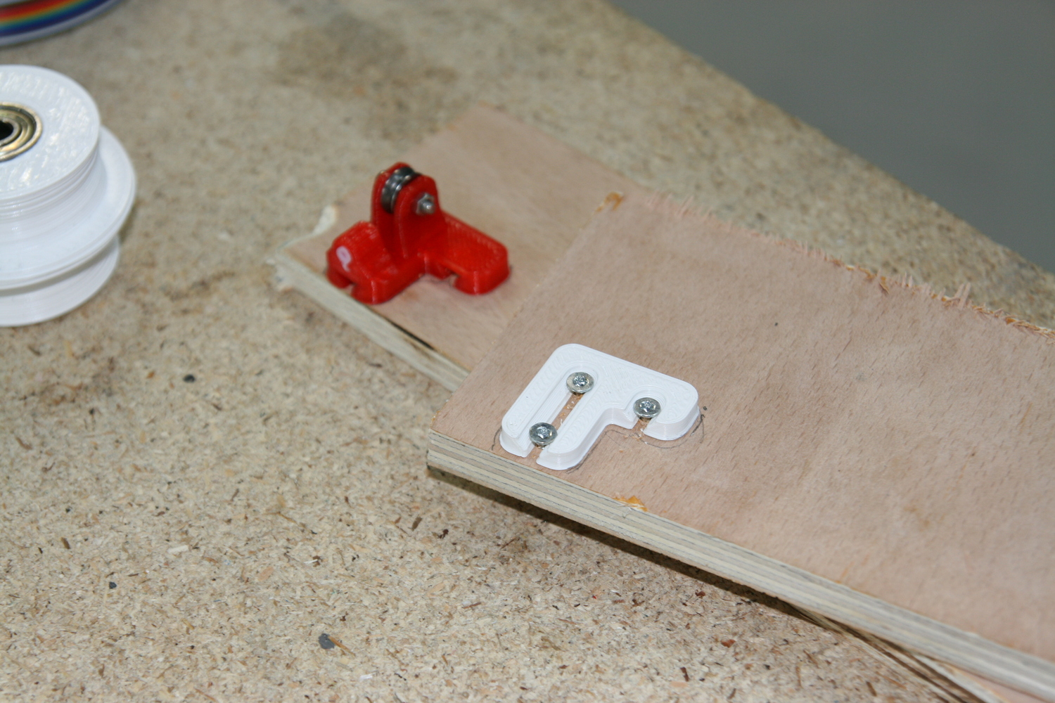
The line path inside the new anchor lineroller for ABC.
The purple circles mark out vgroove bearings.
Upper line goes to the ceiling unit.
The end of the line that comes back from the effector is not tied to the lineroller.
It disappears out of the left edge of this image.
... and are tied together. Knot shown in red in this image.
Tying the lines together like this lets you rotate your effector around Z by hand to line it up with your anchors.
Lastly, a little video of the printer running with the doubled mechanical advantage.
With the added mechanical advantage, I got far less ringing.
Prints done at 70 mm/s came out with much less ringing than the ~30 mm/s printed octupus depicted above, so the improvement
was significant.
Sadly, my camera broke, and I didn't bring my prints with me home from England,
so I can't show you pictures yet.
If you're going to try the doubled abc-lines at home, use
the doubled_abc dev branch over at Gitlab.
And remember to configure your mechanical advantage and correct line lengths in Marlin's Configuration.h.
- tobben
Torbjørn Ludvigsen
I got the chance to test out E3D's coming Super Volcano hot end recently.
The high melt rate let me try to print really fast for the very first time.
At first, I just upped the speed, and it looked like this:
HAWS Replicating and Anchor Template
15-5-2018
In preparation of the Hangprinter Assembly Workshop (HAW), I tested out the Hangprinter Assembly Workshop System (HAWS)
recently.
I'm fascinated by self-replication in software as well as in hardware, so I made Ubuntu run HAWS as a virtual machine that
copied itself onto a USB stick that could then be mounted.
Sort of a parasitic strategy.
I recorded the whole thing as documentation:
I also did another video where I create a new Hangprinter part in HAWS.
The part CADded in the above video has already proved to be handy during anchor assembly.
Use an assembled mover (effector) to space out a pair of anchor linerollers.
Screw your template parts down with three small countersunk screws.
Put two of the screws in the very bottom of the tracks, and put the third somewhere along the long track.
Tighten all three screws nice and snug before you unscrew all of them by about a quarter of a turn.
Your template should now easily slide loose, and your anchor lineroller should easily slide onto the screw heads.
Now, there is a lot more than templates and OS work going on in the Hangpriter Project.
Yesterday, I did my first successful test print with the Super Volcano hot end over at E3D's headquarters in Oxford:
The deposition rate of ~250g/h is very promising.
I hope we'll be able to go even faster, as print times currently limits the practical usefulness of the Hangprinter.
For more live updates (and a link to a live stream directly from the ceiling of E3D HQ) do check out my Twitter.
- tobben
Torbjørn Ludvigsen
In preparation of the Hangprinter Assembly Workshop (HAW), I tested out the Hangprinter Assembly Workshop System (HAWS)
recently.
I'm fascinated by self-replication in software as well as in hardware, so I made Ubuntu run HAWS as a virtual machine that
copied itself onto a USB stick that could then be mounted.
Sort of a parasitic strategy.
I recorded the whole thing as documentation:
How to Build a Temporary Hangprinter Frame
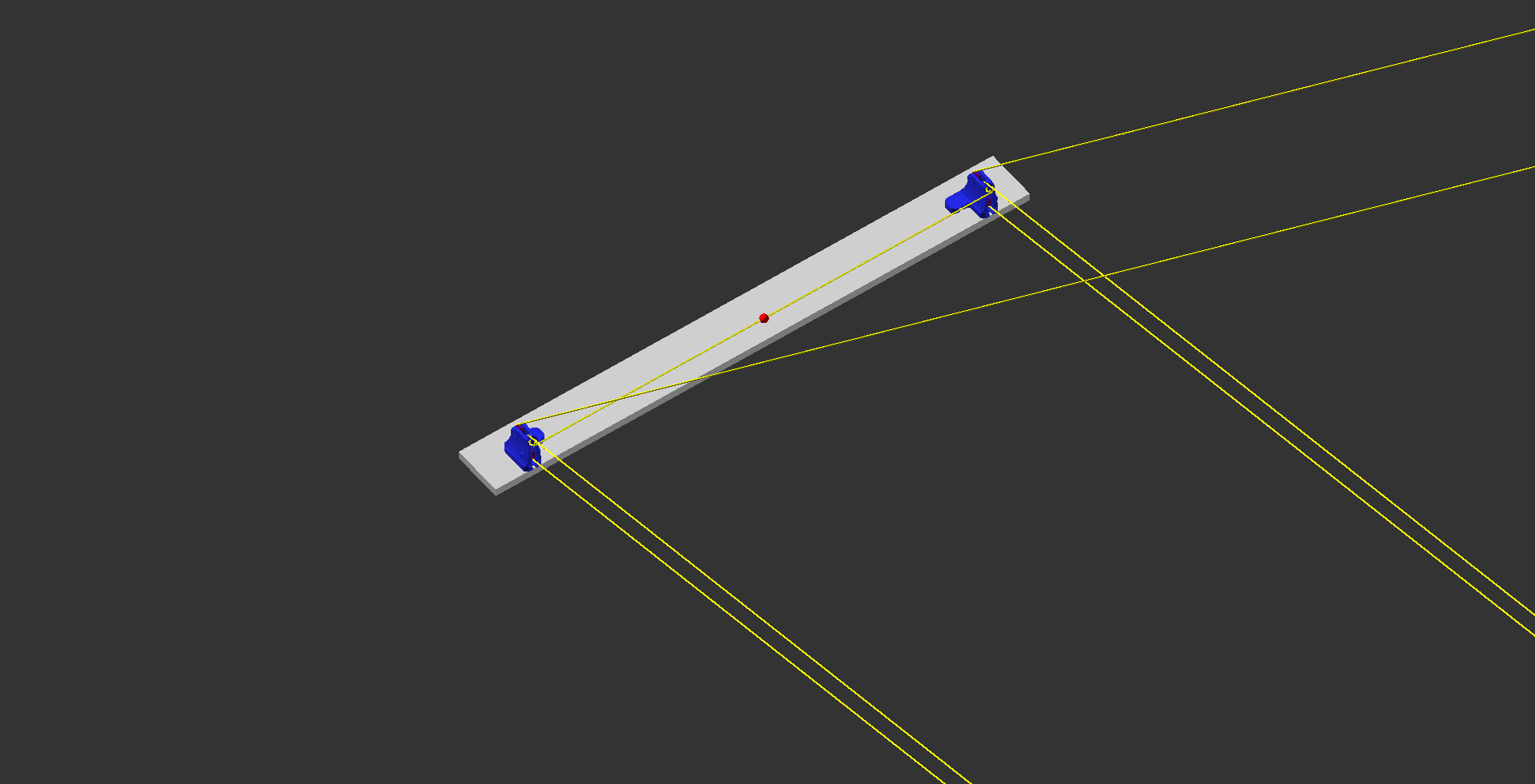
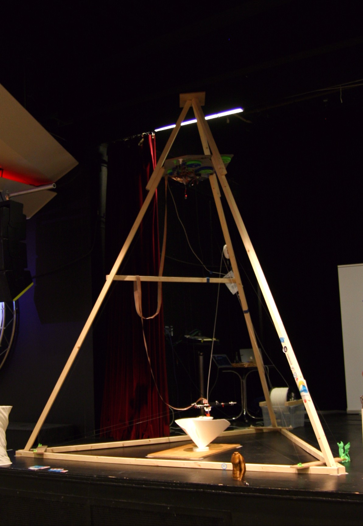
19-4-2018
I demoed Hangprinter v3 at the 3D Meetup Sweden recently.
I could not mount it in the ceiling of the venue, so I had to build a temporary frame.
Knowing how to whip up a temporary Hangprinter frame is useful, so I'm documenting it here.
This is the temporary frame I'm talking about.
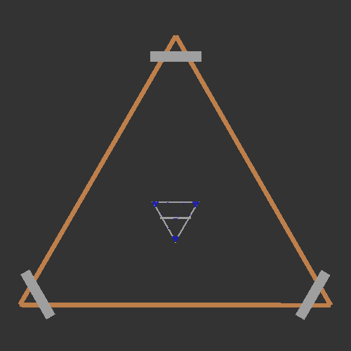
The shape is called a tetrahedron.
It's very nice for a Hangprinter frame, because even if you can wiggle the individual standing beams, all four corners
stay (very close to) stationary.
If I were cooler, I would mount my D-anchor on top of the tetrahedron.
It would be more stationary there.
Bill of materials:
7 pcs 45x45x3000 mm wooden beams
50 pcs ca 4x65mm wood screws
1 small (ca 200x200 mm) top plate sheet
Your Hangprinter's D-anchor (ceiling plate) and 3 ABC-anchors sheets
1 print bed
Required tools:
Hand saw
Cordless drill
A friend to help you out with the last step
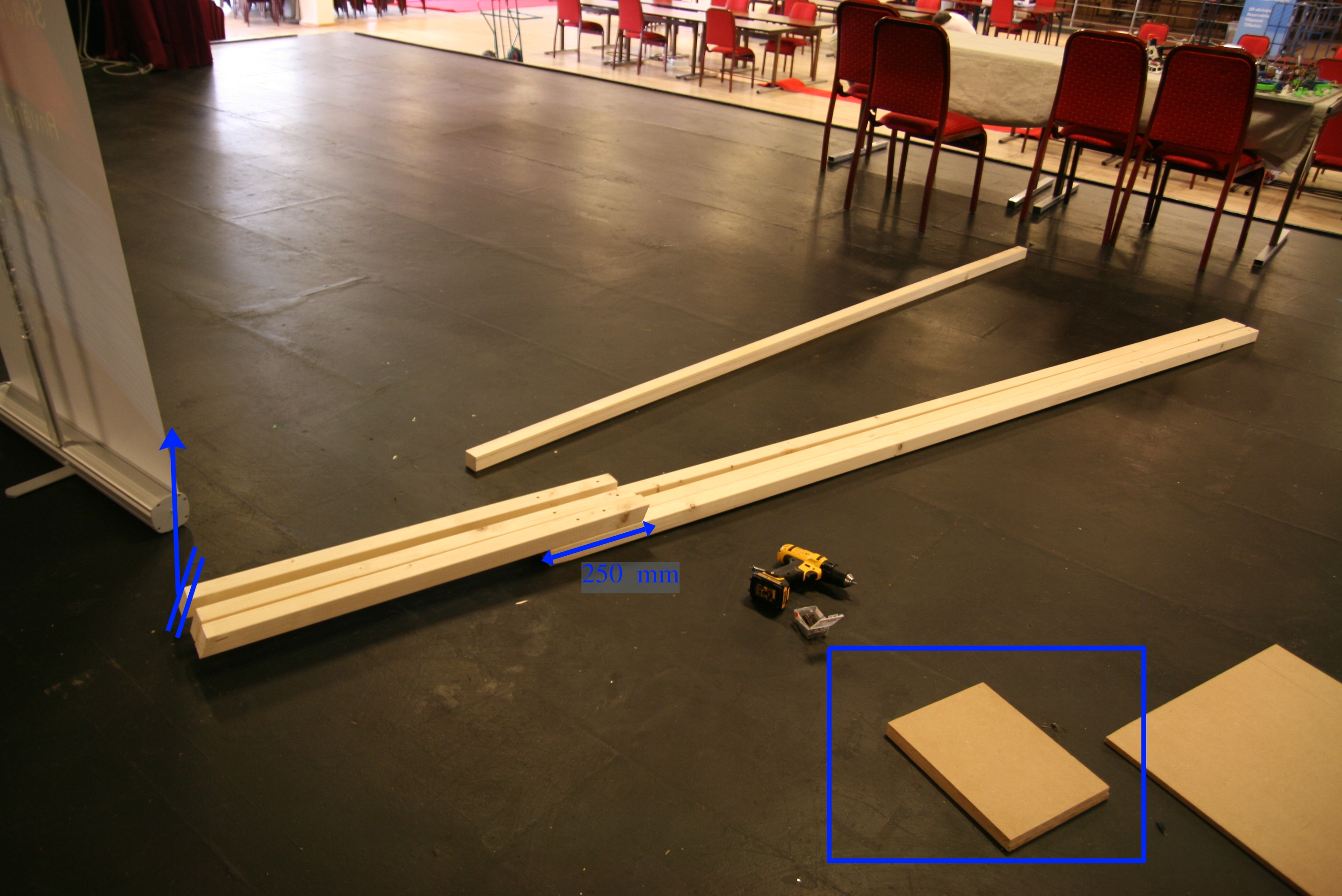
Step 1: Make an equilateral triangle out of three beams
Fixate its shape by screwing down ABC-anchor sheets in each corner, four screws in each sheet.
The rectangular sheet in the middle of this picture is the print bed.
Step 2: Prepare your three standing beams
1 beam has been cut into 3 equal parts.
Cuts have an angle of ca 20 degrees.
Make sure the cut is facing away from the longer beam before screwing together.
See the upwards pointing arrow in the left side of the picture.
The beams' overlap is ca 250 mm long.
Screw from both sides.
To the right in the picture you see the top plate sheet.
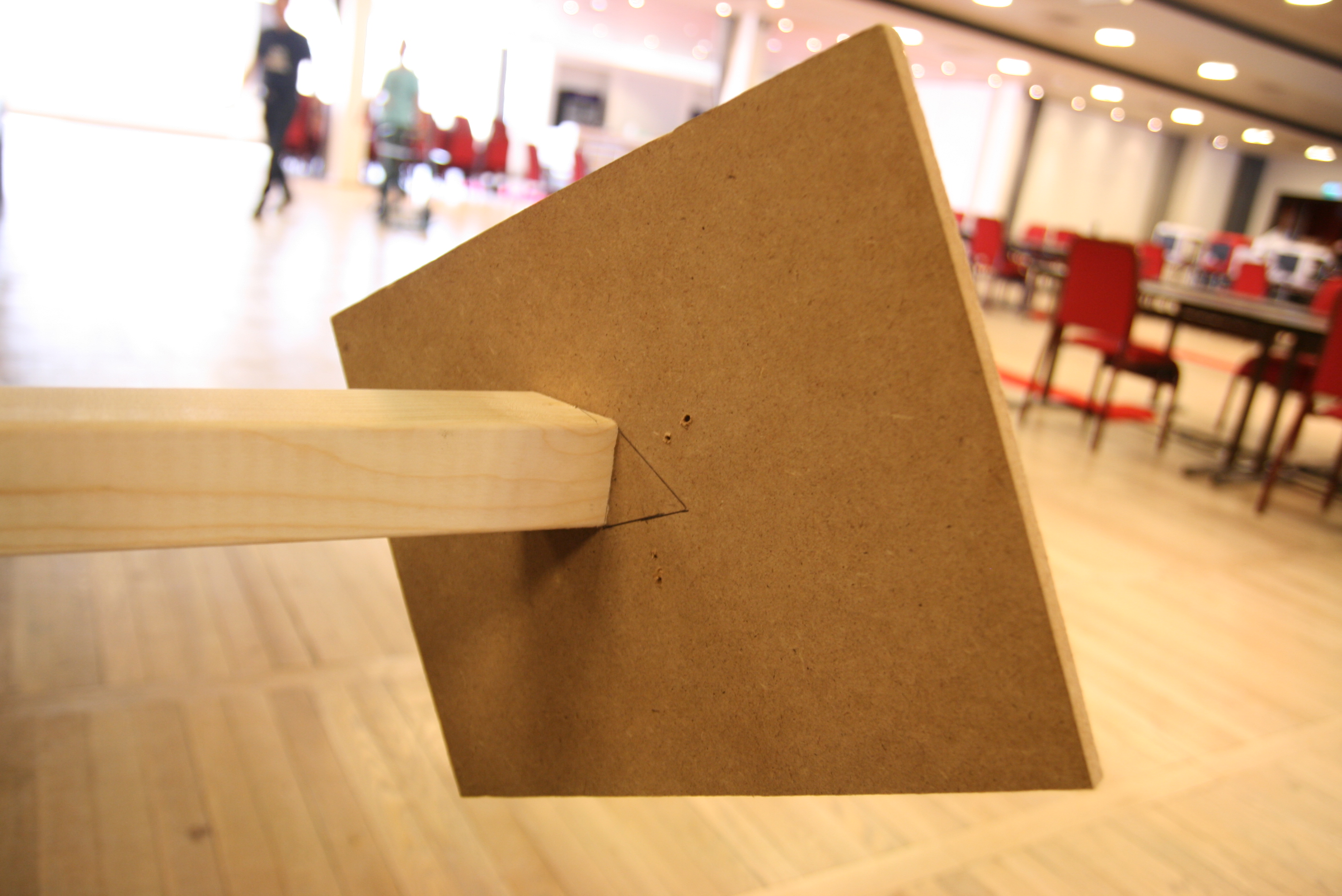
Step 3: Screw standing beams onto the top plate sheet
Attach screws through the top of your top plate sheet and down into the angled end of the standing beams.
Make the angled ends support each other around a central point.
This is what gives the tetrahedron its stiffness.
When attaching the third standing beam, you need your friend to hold it in place, so it doesn't break your top plate sheet.
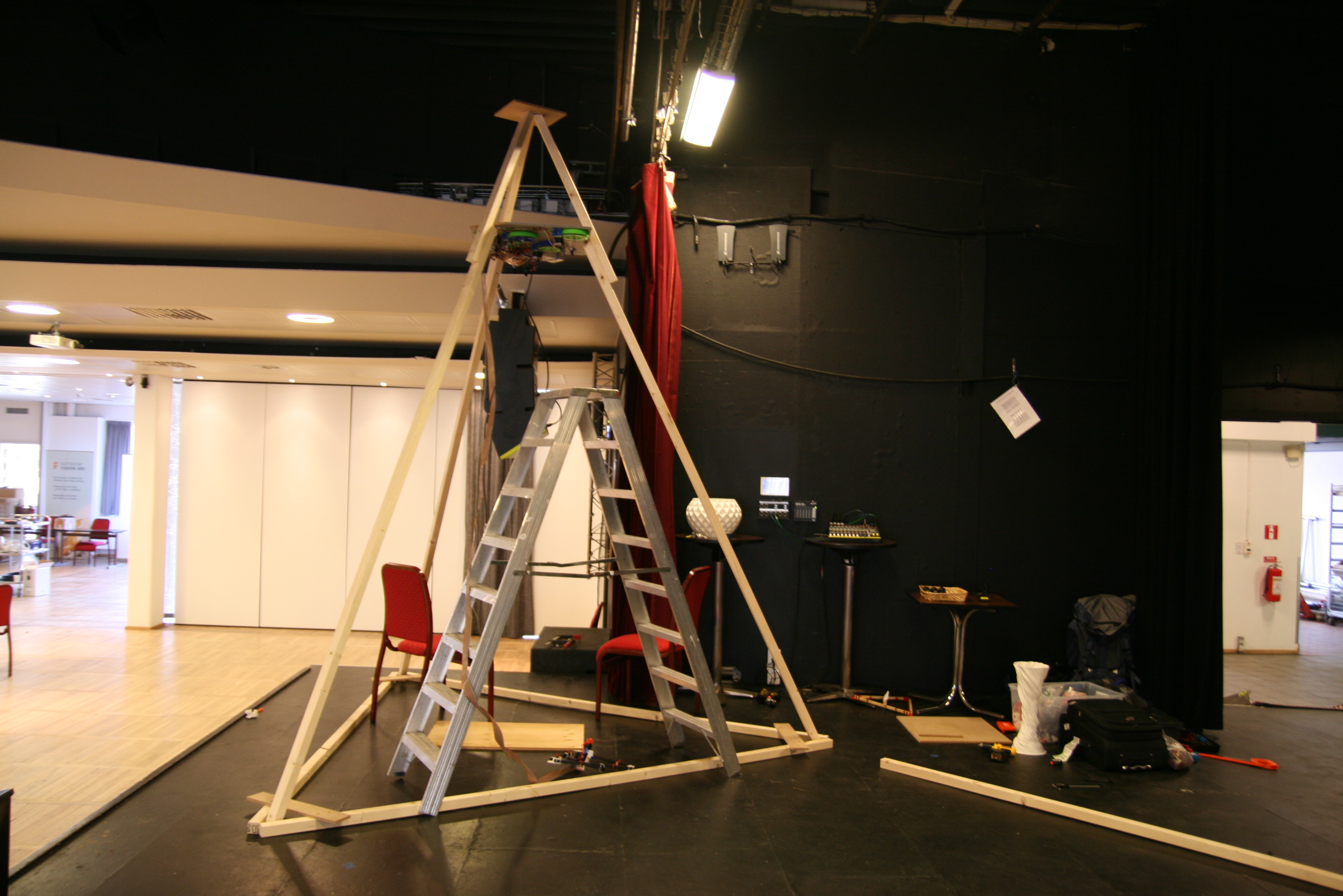
Step 4: Temporarily mount your standing triangle
Secure the three legs of your standing triangle into your corner pockets, like this.
Don't attach them with screws yet.
Sorry that I don't have images of attaching the two other legs and raising the triangle.
You and your friends will have your hands full while doing this.
Step 5: Mount your D-anchor
This is the most tricky step.
Have your friend lift one standing leg out of its corner pocket, and bend open the top triangle.
Wedge your D-anchor in there and close by putting the standing leg back into its pocket.
Step 5: Get the orientation right
See if you can rotate your D-anchor so that your mover will hang roughly 60 degrees rotated compared to your bottom plate.
As long as you're within ca 45-75 degrees, your printer will work perfectly, but you will have to rotate your ABC anchors
accordingly.
When your print head is touching the origin you must fulfill these requirements:
Each pair of ABC-lines must be of equal length. Use measurement tape.
The three D-lines must be vertical. Use a laser level or an aiming plumb.
Step 6: Secure and mark everything up
Now you're done, you just want to make sure it stays the way it is.
Secure your triangle legs to your corner pockets with screws.
Mark up the origin point on the bed surface.
Mark the position of your print surface on the floor with tape or similar.
Mark the position of your frame's corners on the floor with tape or similar.
This image shows how I've marked my bed position on the floor.
The bed itself is heavy enough to not drift around, so it's not actually attached to the floor.
I do similar markings around the frame's bottom triangle corners.
Big thanks to my dad for coming up with this frame design while me and Fred were running around him like chickens in the
middle of the night before Maker Faire Rome 2017.
- tobben
Torbjørn Ludvigsen
I demoed Hangprinter v3 at the 3D Meetup Sweden recently.
I could not mount it in the ceiling of the venue, so I had to build a temporary frame.
Knowing how to whip up a temporary Hangprinter frame is useful, so I'm documenting it here.
Presenting HAW-Nemesis
20-3-2018
Hangprinter Assembly Workshop Nemesis is an operating system that you put on a USB-drive (size 4GB or more).
It boots directly from the USB-stick, and loads itself into RAM memory.
The hard drive of your computer will not be touched.
It contains all the computer tools that I use when I use and develop Hangprinter, and Hangprinter related programs.
It will be given to participants of the forthcoming series of Hangprinter Assembly Workshops.
The following video shows everything working on a virtual machine (VirtualBox) with 3 GB of RAM:
The first screen is what you'll boot into.
If your USB stick supports it, then you can choose to save changes.
Otherwise, your changes to files will not be saved upon reboot.
The video mostly consists of me clicking buttons to demonstrate that things work.
Auto-calibration demo starts at 17:00.
It's packaged as an iso-archive, available here.
Extract the contents of the archive to a USB stick.
I use Archive Manager for this job.
Then execute boot/Porteus-installer-for-Linux.com (or boot/Porteus-installer-for-Windows.exe),
and follow the instructions to make your USB stick bootable.
Pro tip: If you're comfortable with formatting your USB stick, format it to ext4 before extracting the iso.
It will enable you to save your changes.
Now, reboot your computer and get into BIOS.
Usually repeatedly pushing F2, F10, or ESC during reboot does that.
Otherwise, a web search on "boot from USB your computer model here" is recommended.
More Help
The iso-image is build from the Porteus with Arch packages called Nemesis.
Some recommended sources of further information are:
Bring down the threshold for new Hangprinter users.
Give Hangprinter developers a common computing environment.
A test of the fore-runner of HAW-Nemesis, called D3D-Porteus,
is motivated and described in my Master's thesis.
It also contains lots of advise for future development that are not yet implemented.
HAW-Nemesis will see continued development as I collect experience from my series of workshops.
Other News
The first of those workshops are already planned together with RichRap and E3D!
Read more and buy tickets here: eventbrite.com.
I've opened two Hangprinter Merchandise web shops.
One for Sweden (hope it works in all of Europe): spreadshirt.se,
and one for the USA (hope it works internationally): spreadshirt.com.
- tobben
Torbjørn Ludvigsen
Hangprinter Assembly Workshop Nemesis is an operating system that you put on a USB-drive (size 4GB or more).
It boots directly from the USB-stick, and loads itself into RAM memory.
The hard drive of your computer will not be touched.
A Little Work on Line Flex
21-2-2018
Today's Hangprinter firmwares assumes no flex at all in the movement axes.
This is obviously a very rough approximation.
In reality, all Hangprinter axes act like springs.
Accounting for this can win us several millimeters of accuracy near the limits of our reachable print volume.
Solutions
Some flex comes from line modulus, but adding infinitely stiff lines alone won't solve our problems because ceilings, floors,
ceiling unit sheets and plastic parts also flex.
Very stiff lines are also thick, building more on the spools and making the imperfection of our buildup compensation more
severe.
Another brute force solution would be to closely monitor the mover and constantly compute and execute ad-hoc compensation.
This could be made to work well, but it would add to hardware cost and complexity.
A third solution is to include flex in the firmware's internal model of the movement system.
This keeps hardware simple.
Configuration overhead must be minimized by using standardized parts and providing scripted and straight forward instructions.
It would be possible completely circumvent configuration overhead by collecting flex data with force sensors.
This would require extra hardware, which in turn would have to be configured.
It is in the spirit of the Hangprinter Project to make hardware additions beyond the bare bones setup optional,
and solve as much as possible in software.
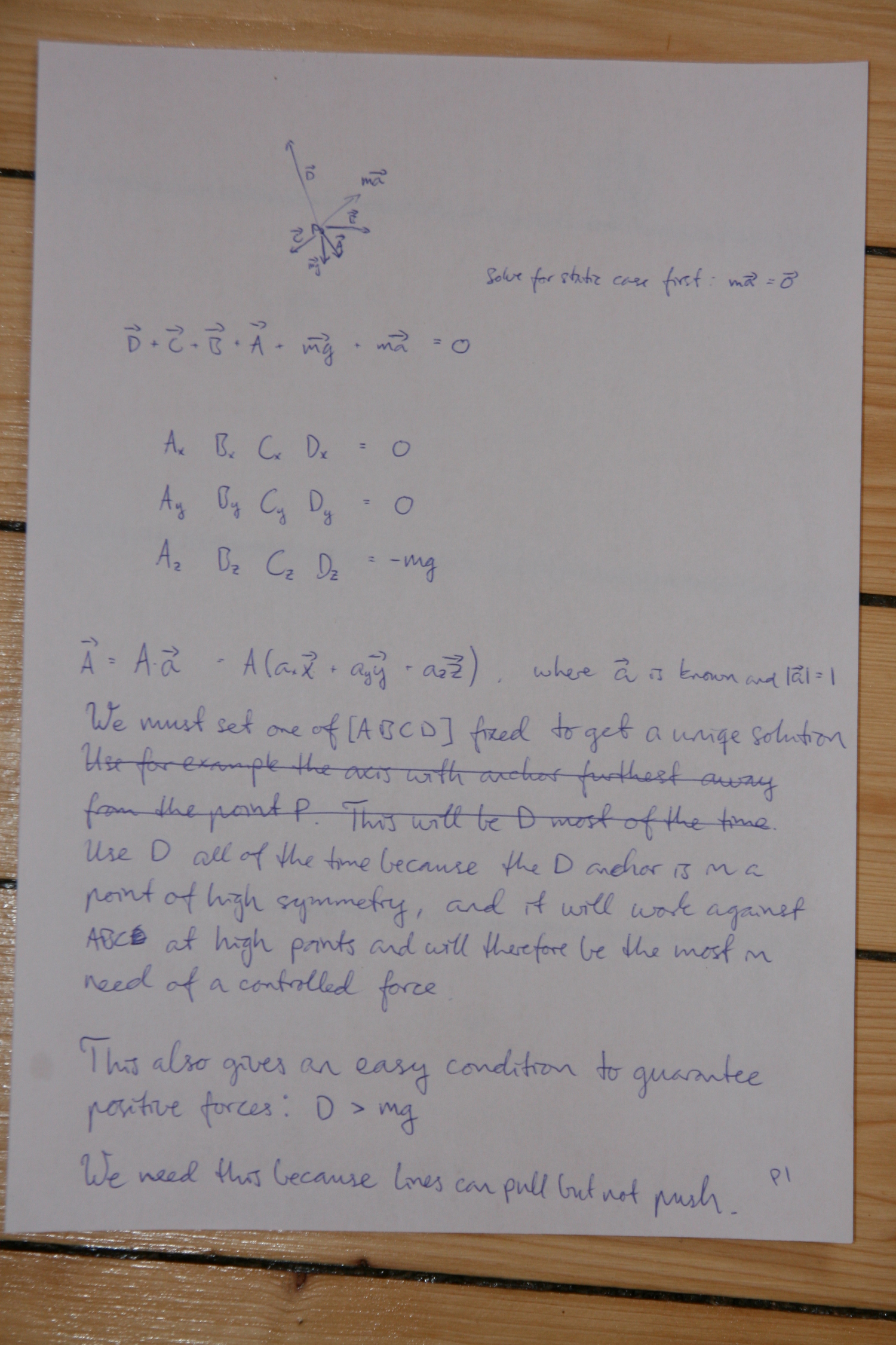
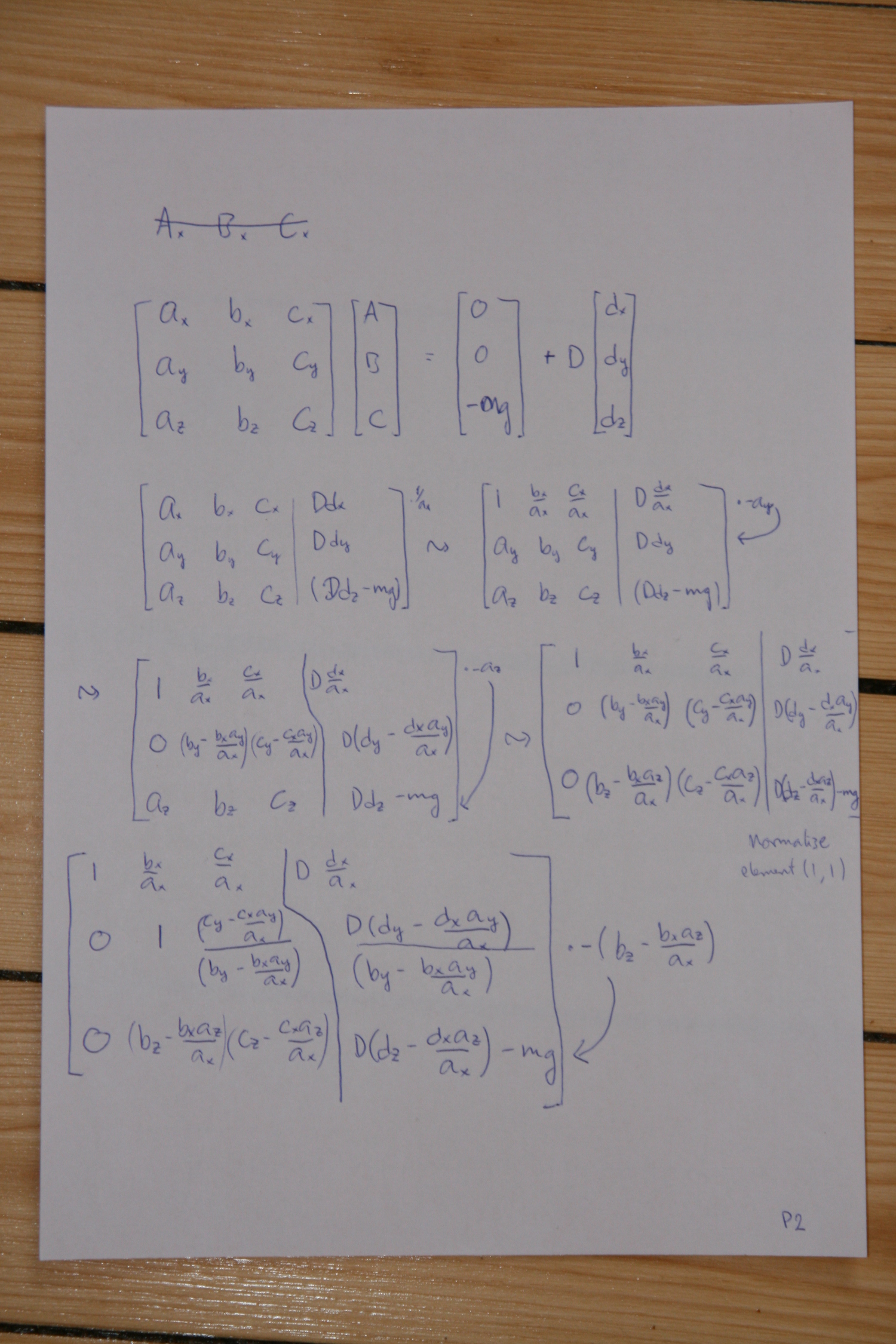
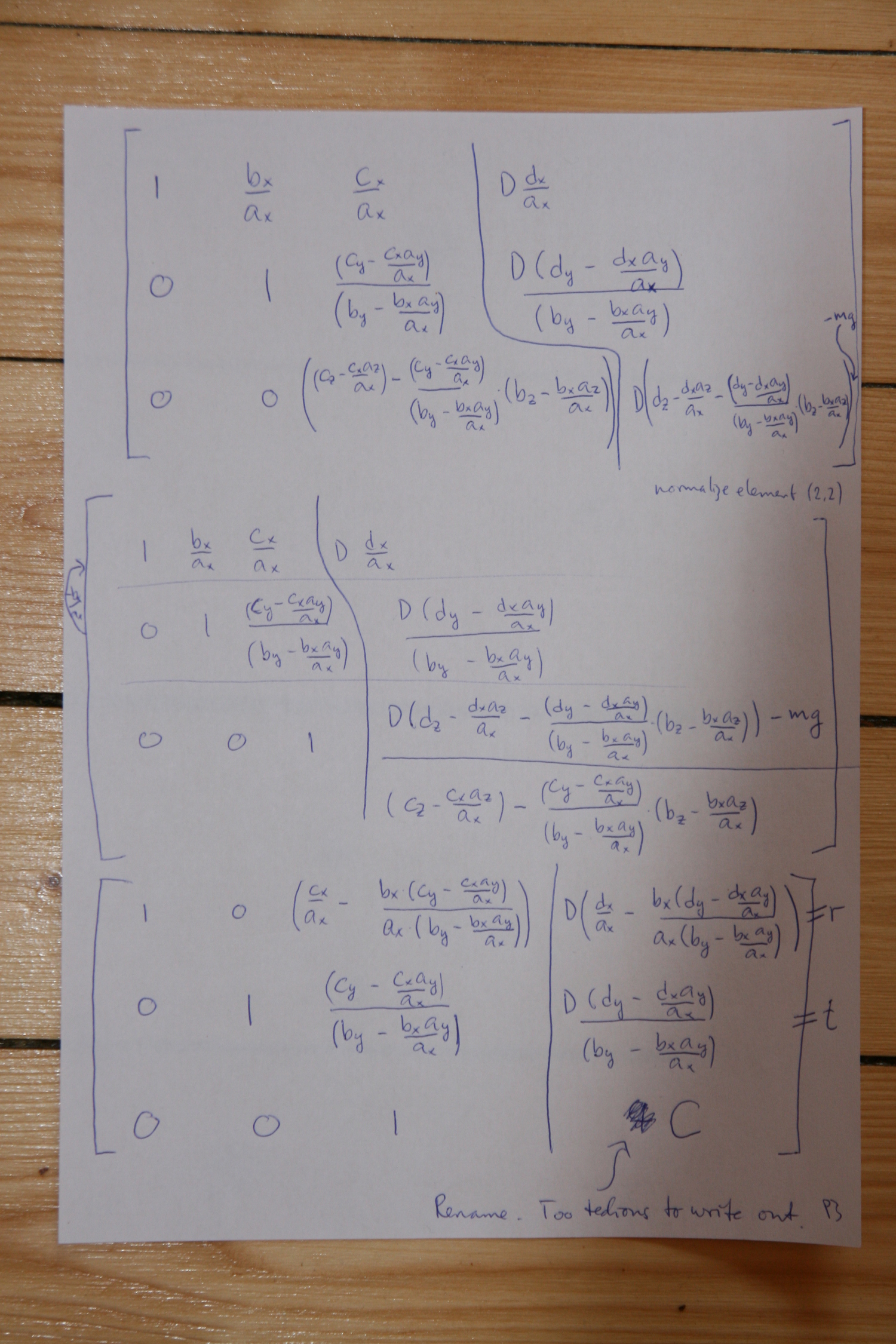
Use The Force
The scribbles below derive how to synchronize the four forces from the four motors,
so that all lines can be tightened or slackened, without moving the mover.
A force magnitude can be approximately mapped to a line shortening/elongation by using Hooke's law,
where a guessed or measured Young's modulus gives the spring constant \(k\).
Note that the spring "constant" will vary with line length in our case.
The no-flex line lengths that current firmwares calculate can be used to calculate a new line length that does (approximately)
account for flex:
\begin{equation}
l_{acc} = l - F/k(l),
\end{equation}
where \(l_{acc}\) is the new line length that accounts for flex, \(l\) is the line length calculated and used by current
Hangprinter firmwares, \(k(l)\) is the spring constant of the suspended line, and \(F\) is the desired force to be exerted
by the line.
The four different forces \(F\) are called \(A\), \(B\), \(C\), and \(D\) in the derivation/scribble notes below.
The mover is approximated to be a point mass.
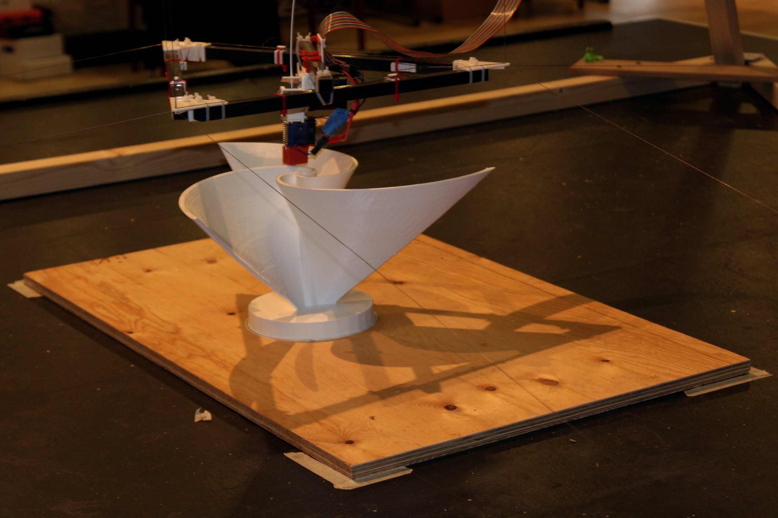
The six forces acting on the mover are drawn out in a beautiful hand made 3d visualization.
It is not true that we must set one of \([ABCD]\) fixed.
That is just one of many possible ways to constrain the system.
Setting \(D=|\vec{D}|\) to be constant was just the most useful constraint I could come up with.
Note that \(m\vec{a}\) will not be zero during a print, since the mover will be moving around.
It is however easy to re-introduce into the calculations below, right beside \(m\vec{g}\) and \(\vec{D}\).
Thanks to my professors for drilling me in manual Gaussian elimination.
I never thought I would get to use it for something actually useful.
Maybe I shouldn't use it.
There's always sympy.
There are our expressions for the magnitudes of the (zero-acceleration-case) force magnitudes \(A\), \(B\), and \(C\).
Lots of divisions. Probably not simple enough to be done on a Atmel2560.
So... What to do?
As my professors always told me:
"Taylor expand, my good boy.
Taylor expand for the sake of glory and honor!
Taylor expand, and use only the first two terms, because everything ... Yes! EVERYTHING worth fighting for can be approximated to be perfectly linear!
I tell you, boy, if you ever ever feel doubt in your heart, just Taylor expand, and your problems will all be cake."
Ok, they didn't quite say it like that, and maybe we should use three terms, but I'll save you the expansion for another
post.
If you're so excited right now that you want to Taylor expand yourself: do it around the origin, and remember that
where ANCHOR_A_X is non-existent by convention,
ANCHOR_A_Y is the y-coordinate of your A-anchor,
ANCHOR_A_Z is the z-coordinate of our A-anchor,
and \((x, y, z)\) is the position of your mover relative to the origin.
Also remember to handle the cases when denominators are zero in a graceful way.
Fancy new 32-bit CPUs can probably compute the full expressions, but they can't handle division by zero.
Best regards,
- tobben
Torbjørn Ludvigsen
Today's Hangprinter firmwares assumes no flex at all in the movement axes.
This is obviously a very rough approximation.
In reality, all Hangprinter axes act like springs.
Accounting for this can win us several millimeters of accuracy near the limits of our reachable print volume.
Consequences of Miscalibrating Anchor Positions
28-1-2018
I made a script recently, to get learn how a Hangprinter axis with bad anchor positions behaves.
The script itself is here.
The Quick Take-Away:
Moving directly from/towards an anchor gives small errors, almost regardless of calibration errors.
The Details:
Four plots are shown below.
Only the XY axes are shown, but the results are similar in three dimensions.
Line length errors in different XY-positions are shown with color codes.
They are normalized so that the error in the origin is 0 in all plots.
In negative areas, the mis-calibrated axis will over-tighten.
In positive areas, the mis-calibrated axis will let out too much line.
Click the plots to get larger versions.
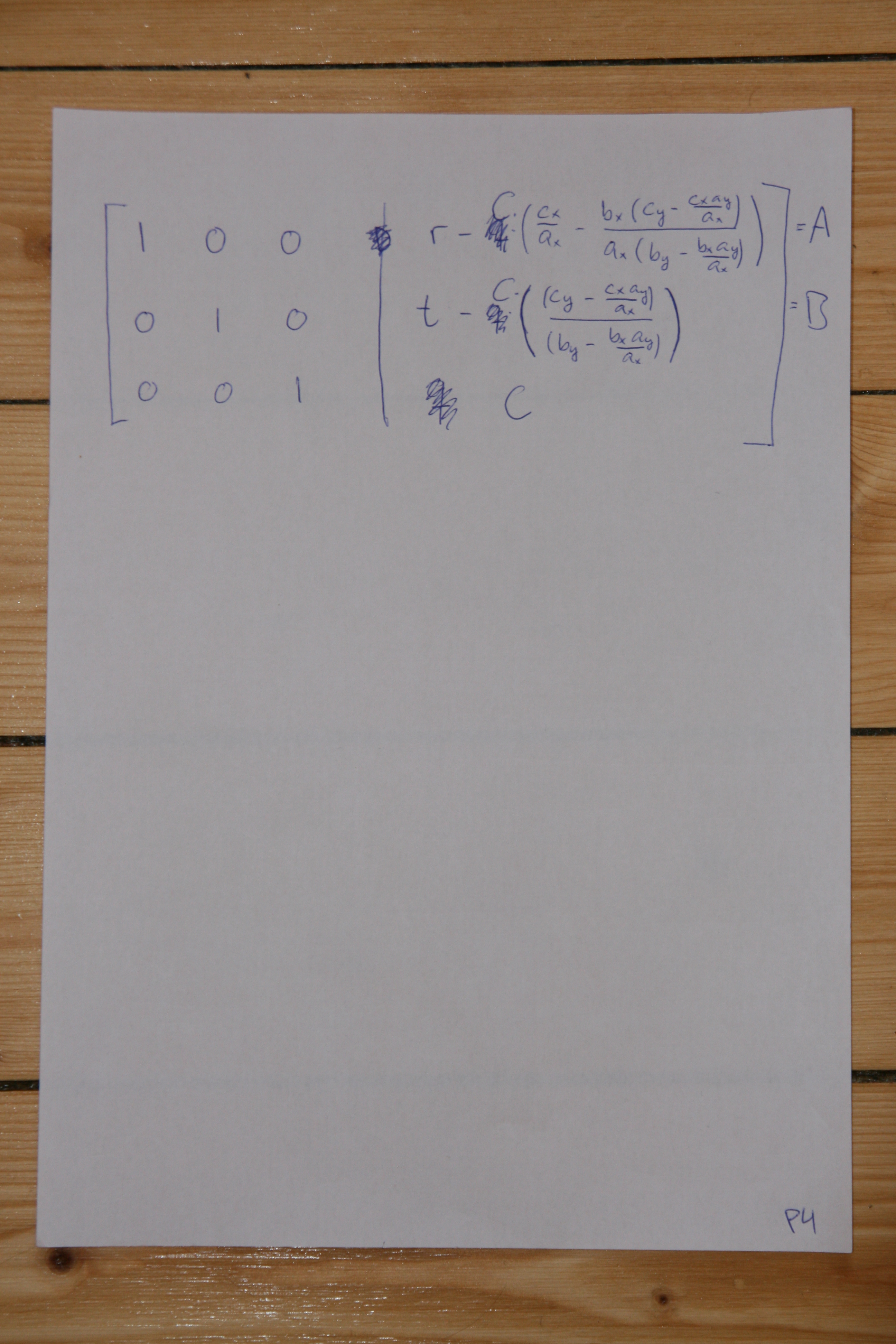
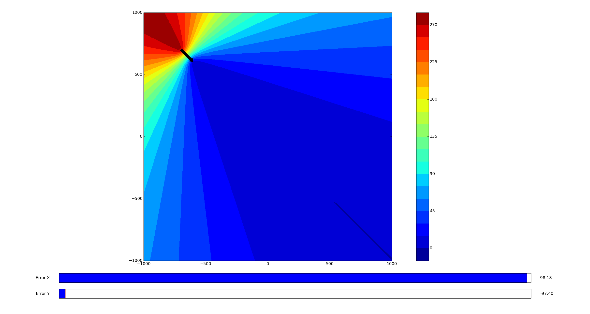
In this plot, the anchor is located at (-700, 700).
The black arrow shows a measurement error of (-97, -97), so the machine has been configured with anchor locations (-797,
603).
In the point (-500,0), this mis-calibrated axis will end up with 65 mm too short lines.
In (0, 500) however, it ends up with 65 mm too long lines.
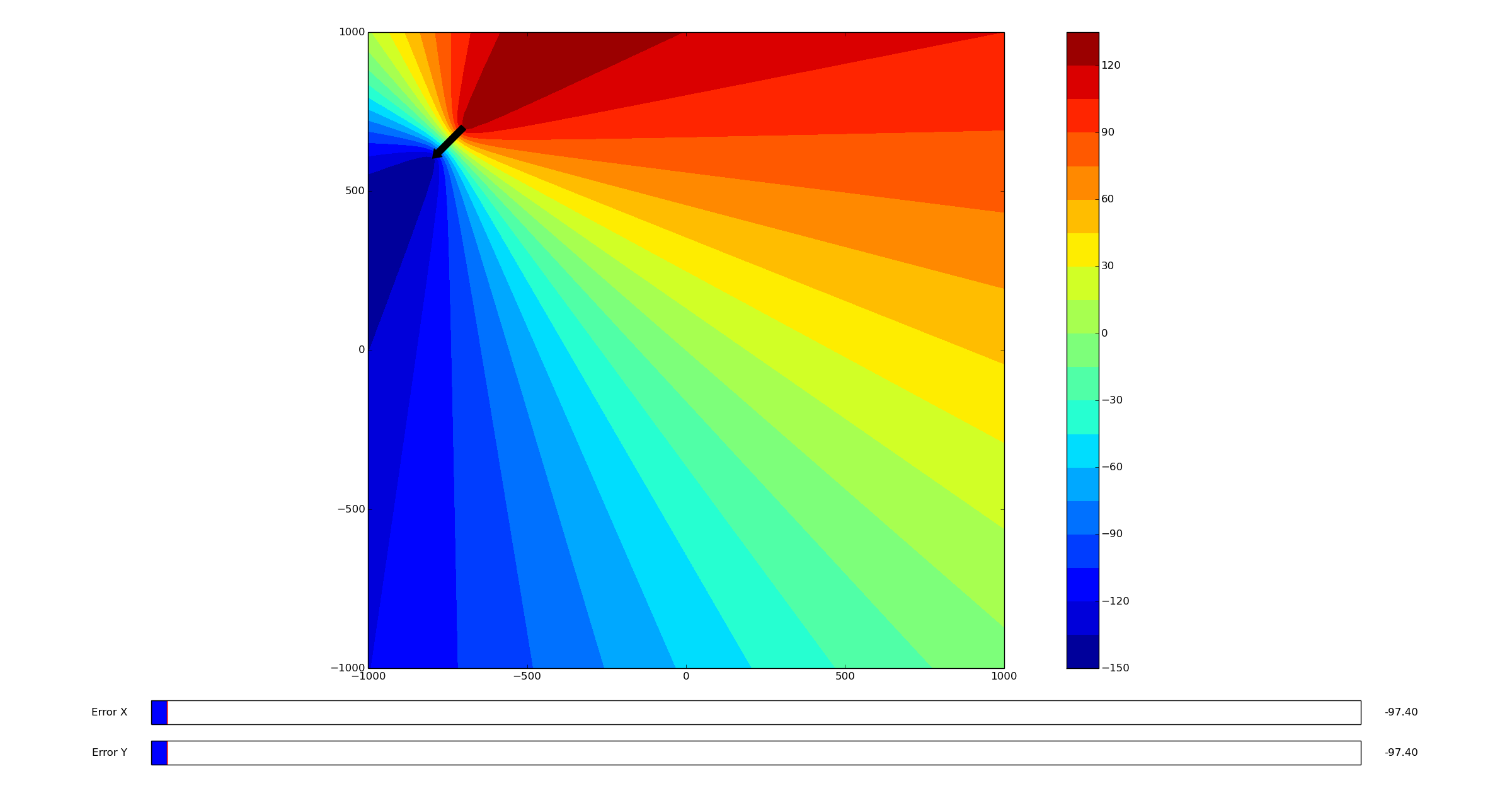
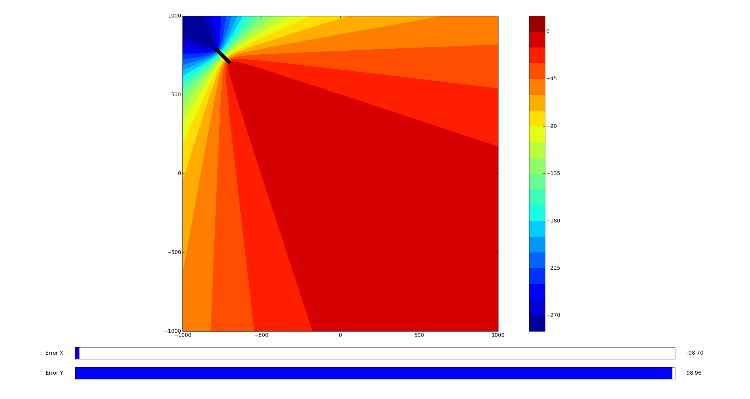
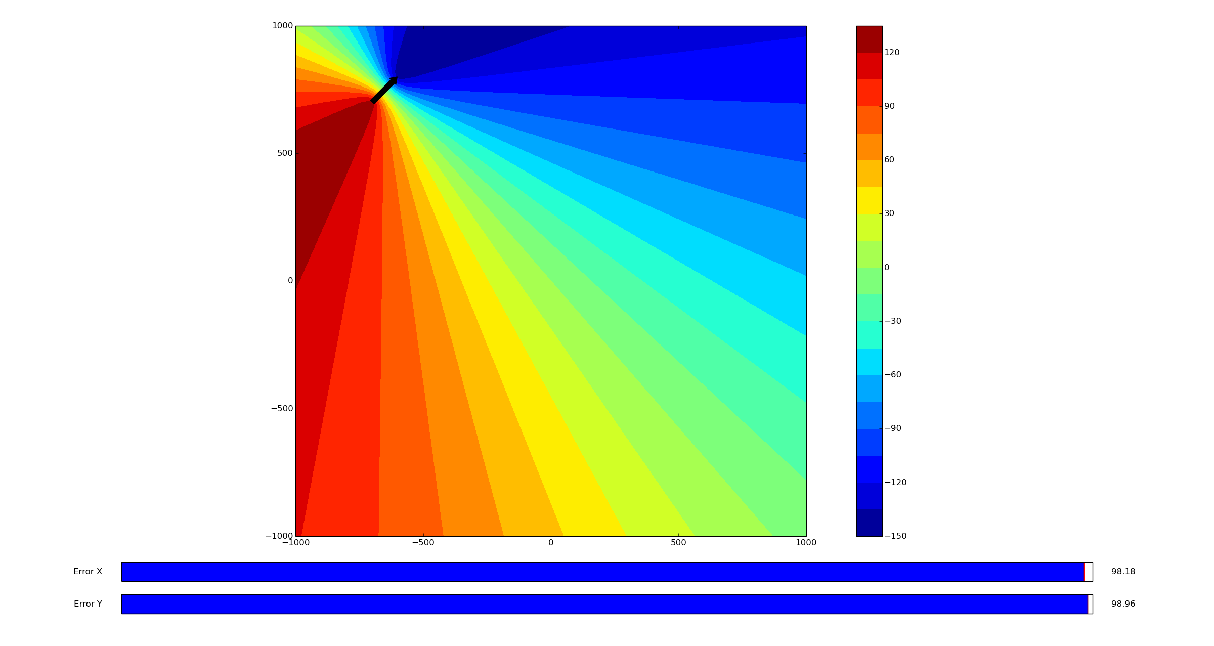
Anchor location: (-700, 700)
Measurement error: (-99, 99)
Configured anchor location: (-799, 799)
Error at (-500,0): 15 mm too tight
Error at (0,500): 15 mm too tight
Anchor location: (-700, 700)
Measurement error: (98, 99)
Configured anchor location: (-602, 799)
Error at (-500,0): 67 mm too long
Error at (0,500): 66 mm too tight
Anchor location: (-700, 700)
Measurement error: (98, -99)
Configured anchor location: (-602, 601)
Error at (-500,0): 21 mm too long
Error at (0,500): 22 mm too long
- tobben
Torbjørn Ludvigsen
I made a script recently, to get learn how a Hangprinter axis with bad anchor positions behaves.
The script itself is here.
New Extruder Holder Bracket
18-1-2018
I've converted the extruder_holder bracket to be ziptie based like the rest of the mover:
Render of the new extruder_holder.
It is a great deal sturdier than it's screw-clamping predecessor.
I tested lots of little tweaks to find the stiffest solution around all axes.
Four slightly different extruder holders lined up for flex testing.
The motor was possible to tilt downwards no matter how I changed the model it seemed.
The winning tweak turned out to be adding a third ziptie first.
Like this:
And to tighten the third ziptie with a wedge.
Like this:
The end result is dead sturdy and looks like this:
All new files and are published to the working branch of the repo: Openscad_version_3.
- tobben
Torbjørn Ludvigsen
I've converted the extruder_holder bracket to be ziptie based like the rest of the mover:
Ziptie Mover
3-1-2018
I've implemented Tom's suggestion to use zipties on the mover corners.
Ziptied mover.
Using zipties in stead of screws has some advantages.
Works with beams of different widths (currently 12.5 to 17.5 mm).
Does not rely on flexing fragile printed parts.
Saves some weight.
I also find it easier to assemble since there are no fiddling with small screws and nuts.
Ziptied mover corner.
The zipties' heads wrap around the sharp corner of the wooden beam.
Zipties of width 4 mm gives the most sturdy mover, but I've found sizes down to 2.4 mm (like in this picture) to work well.
For wooden movers, I've also thrown away the old beam_clamp.
It's both more sturdy and lighter to just clamp the crossbeam with a little M3 screw and nut.
Note that I pre-drilled 3.2 mm holes before inserting the M3 screw.
I use washers on both sides of the hole because the pine wood is so soft.
These two improvements combined save ca 60 g of weight compared to the previous mover.
I've also added a little nutlock to beam_slider, to make it easier to tighten/untighten with one hand.
More improvements inspired by what I learned in Hamburg is in the pipeline.
Happy new year!
- tobben
Torbjørn Ludvigsen
I've implemented Tom's suggestion to use zipties on the mover corners.
The Why Again
7-12-2017
This is the 50'th Hangprinter blog post, and I think it's a good opportunity to elaborate on why I develop Hangprinters.
Read more...
Time for Clones
15-11-2017
It's been a busy month and the next one will be busy too.
I've helped fredrudolf build a v3.3 (aka HP3).
We're preparing a live demo at Maker Faire Rome (Dec 1-3).
After that, I will help Tom create a video series on Hangprinter.
Read more...
Version 3.3 In The Making
14-10-2017
It's been a month of very technical development.
I feel like I'm searching for the version 3.3 among a forest of new ideas and insights.
Read more...
The Hangprinter v3 has developed very quickly recently.
We've been developing so intensely, we almost forgot to print a Benchy with the current prototype, called v3.2.
Read more...
Closed Loop Doing its Job and Sstruder v2 Pic
6-7-2017
This video shows how the closed loop ABC axes act like springs when hot end meets an obstacle.
Read more...
Working on Auto Calibration and Reliability
3-7-2017
I put together a closed loop single unit Hangprinter with pancake steppers recently.
The following video shows that it can run upwards along the D-line at 26.6 mm/s.
Read more...
Walking the Line
4-6-2017
Following up on what I planned 35 days ago:
"When the version 3 is up and running, I will focus my dev time on adding
closed loop control,
auto calibration
and DC motors, in that order.
Read more...
Experimental Dual Unit Designs
30-4-2017
The Hangprinter Hackathon at Bitraf produced some technical progress.
Read more...
Other People's Hangprinter Builds
25-4-2017
This beauty was posted by Mario Lucas here.
This impressive bottom plate was posted by
Jonathan Bahrs
here.
Read more...
In this forum post,
NOVAprint confirmed what I had suspected was a weakness in the sandwich design.
A gap might open between the snelle and the sandwich gear, so that line wraps around the center cylinder.
I never really liked the super-short screws in the sandwich either, so I've designed a push fit solution:
Read more...
Sstruder v2 and Helsingborg
27-3-2017
I got the chance to test the improved extruder design recently. It worked better than the previous Sstruder, so stls were
pushed to the repo today.
Read more...
Tweets
7-3-2017
I posted a few Tweets recently. Reposting them here now.
Read more...
The Tilt Problem
26-2-2017
Hello Reprappers and Hangprinterers!
The Babel print gives a lot of lessons, so there's a lot of posts this week.
Ca 1.5 m above ground and with 20 m of line on the D-spool, I've noticed a previously undocumented problem.
Read more...
Changed Anchor Points Mid Print
24-2-2017
I managed to sneak up the anchor points yesterday.
The secret trick is to pause and move one anchor point at a time.
Read more...
Slowly but Surely
23-2-2017
920 first millemeters of a Babel Tower in a staircase.
Read more...
Community at Embryo Stage
20-2-2017
It seems like some collaboration and maybe even a little community is gathering around the Hangprinter Project.
Right now, there are 5-6 builders out there wrapping their heads around the source files, assembly process and calibration.
Read more...
D-Wobble Debugged
2-2-2017
Those who have zoomed in on my Hangprints after I added the worm drive will have noticed a periodic error.
Read more...
Experimental Line Buildup Compensation Feature
27-1-2017
I've conducted a few experiments recently,
and I think I've arrived at a usable implementation of the line buildup compensation that I described in
an earlier blog post.
In this post, I'll try to go a bit more in detail.
Read more...
Hangprinter Presentation Video and Campaign
15-1-2017
I've been helped by some friends to make a campaign.
It has a presentation video and a logo and a picture of me and everything!
Read more...
Compensation May Allow Bigger Prints
14-12-2016
The line compensation code may increase print volume noticeably.
During testing, it has allowed Hangprinter version 2 to go places
where version 1 surely would have over-tightened lines and skipped steps.
Read more...
Compensating Line Buildup on Spools
11-12-2016
I've added to Hangprinter-Marlins some code that
compensates for line buildup on the spools.
Without it, I found that error in steps/mm grew to several percent
as print dimensions grew close to 1 m.
The problem was particularly noticeable on the D-axis since it has three doubled lines,
so moving 1 mm in the D-direction puts 6 mm of line on the D-spool.
Read more...
The Worm Drive Works
8-12-2016
Just tested the worm drive.
I was so happy to see it work that I made a little video.
Read more...
Adjustable D Line Lengths and New Look
26-11-2016
Just made the D-line lengths easier to adjust independently.
This is useful to get Hangprinter's corners in level with bed.
Newest changes are at a
new branch in the repo.
Read more...
Worm Drive on D-axis
18-11-2016
The best part is that the worm is pure parametrized OpenSCAD and renders nicely.
Read more...
Another Stop Motion Video
5-11-2016
Hangprinting 0.9 m high twisted P at Teknisk Museum's 3D-printerfestival.
Note: this text was edited on 7-11-2016.
Read more...
Hangprinter Calibration Manual v0.1
3-11-2016
This post will make it easier to calibrate Clerck by avoiding the need for measurements like this:
Read more...
Oslo Skaperfestival 2016
25-10-2016
Clerck was demonstrated in public for the first time this weekend!
Read more...
Homing the Hangprinter Without Adding Hardware
23-9-2016
I've thought some more about Hangprinter recently, since I'm going to demonstrate it on the
3d printer festival
arranged by the Norwegian Museum of Science and Technology in Oslo.
I've only ever mounted and calibrated Hangprinter once before,
so getting the manual homing to work fast enough worries me a bit.
I don't have the time to implement the proposed
accelerometer dependent homing procedure
before the festival.
Read more...
Yet Another Very Simple Extruder Design
21-9-2016
I've thought about a second generation Hangprinter lately, including the extruder.
My current favourite re-design uses two motors running synchronously.
Read more...
Why Optimize Chaotic Production?
10-9-2016
RepRappers have noticed me that basing the story line of my
my Master's thesis
on productivity numbers doesn't resonate with them.
This tickled me to think about and formulate why I do what I do, hence this post.
Read more...
Portable Gcode and Short Status
5-9-2016
Today I asked a question on reprap forums that has puzzled me for a long time.
Why don't we share gcode instead of 3d models?
The technical obstacles are small and it would be an obvious optimization of chaotic production.
See the forum post for details.
Hoping for an interesting discussion there.
Read more...
Optimize Chaotic Production
29-6-2016
I presented my Master's recently, with a story line that was very RepRap centric.
I'd like to re-present and develop my thoughts with some colors here.
Be warned that this is a post about why I RepRap, not how I RepRap.
Read more...
Update and Clerck Build Instructions
8-2-2016
I've been working on Open Source Ecology 3D printer workshops (see my work log for exactly what I've been up to)
the past month, and will continue to work on that until mid summer.
Read more...
Everything on this homepage, except those videos who are published via Vimeo or Youtube, is licensed under the Gnu Free Documentation License.
The videos published via Vimeo or Youtube are also licensed via Vimeo or Youtube.