I had a chat with a motion capture company recently.
As part of getting to known one another,
they asked if I might be one who resell their product in the future.
I said that I would likely remain just a user, but it got me thinking.
It doesn't fit the Hangprinter Project's goals to bundle in their products on my side.
However, they should create a Hangprinter + motion capture bundled product.
It would be an unusually awesome product.
The product would create a whole new market for them,
perhaps new to the world, a market for on-demand measurement data
for precision macinery.
The idea is more general, but I'll explain how it would work for
a hypothetical motion capture company called Company X,
and their hypothetical Hangprinter + motion capture bundle called the Hangprinter+ Bundle.
A Tale Of Good Business
So, Company X sells a cheap Hangprinter bundled with some motion capture equipment
and calls it the Hangprinter+ Bundle.
The Hangprinter+ has a super power.
It becomes super performant and easy to use when it gets fed with high quality pose measurements.
And such pose measurements are sold on demand by Company X.
The customer has the motion capture equipment,
Hangprinter+ has made the data valuable,
and Company X can refine the data and feed it to the Hangprinter+.
There will be a payment, and it could follow any model.
Pay-per-computation cloud service,
software licensing, subscription based, or what have you.
The important part about the payment model is that
it includes a low upfront investment for the customer coupled with
paying on-demand for convenience and performance later.
That way, the Bundle opens up the market for on-demand precision.
A Good Deal for The Customer
Not only is the Hangprinter+ Bundle
dirt cheap compared to similarly sized traditional machines.
It also outsources almost all the specialized knowledge to Company X.
Hangprinter+ calibrates itself and can safely be operated by anyone.
Stellar automation and support is be quite easy for Company X
to implement, given that the machine can be continuously monitored by themselves.
When orders roll into Hangprinter+ users' order books,
they are financially enabled to, and indeed happy to, pay for the
convenience that only high quality pose measurement data can give.
The customer also benefits from Hangprinter's good old selling points,
like capitalizing ceiling real estate and
freeing up all the floor space below it when idle,
being self-replicating, fitting into the wider FFF 3D printnig ecosystem,
all that good stuff.
The Customer Is Not A Traditional Manufacturing Company
Established manufacturing companies go "meh", and highlight that Carthesian gantry
style machines are more compact and contained during use.
And traditional machines don't need on-demand precision.
They are right.
Traditional manufacturing companies have an easy time overlooking the cost of their mostly
idle machines that they already bought, taking up floor space that they already inhabit,
and requiring specialized knowledge that they already have.
Their current traditional products already pay for those things.
Replicating their current products with the Hangprinter+
might even be impossible for them.
Clearing out traditional heavy machines is risky and expensive.
So Hangprinter+
does not capture big market shares from
established lathe, CNC mill, Pick'n'place, large scale 3d printing,
or water jet companies.
On-demand precision rather finds a new market, with customers that
were previously unserved by traditional companies' offerings.
It appeals to those who didn't even think about manufacturing before,
because it was way too hard, expensive, or limited in capability.
Hangprinter+ Is The Core Of A Rich Ecosystem
When the needs or preferences of the customer changes,
they are able to seek another source of pose measurement data,
or create one on their own.
There exists open source alternatives, like hp-mark,
to both put in use directly, and to draw inspiration and learnings from.
Hangprinter+ accepts raw measurement data from any source,
through a well defined and stable API.
It also performs as good as possible without any pose measurement data.
There is no vendor lock-in.
Pose measurements is not the only kind of data that can improve Hangprinter+
performance.
See for example
The Spaghetti Detective
for a data driven service employed in the space of 3d printing.
Hangprinter+ provides APIs for inputting all the kinds of data that
might be generally useful for improving motion control.
In addition to pose data and spaghetti detective data, there's plenty of room
for speed data, line tightness/force data, line directions data, and print quality
so far data.
A Good Deal For Company X
This deal for Company X is also extremely good.
They are able to sell a full, vertically integrated solution
that puts their motion capture competence at the center stage.
Their previous motion capture products were more of a solution looking for a problem.
The Hangprinter+ package is a product they can
specialize further on while still utilizing the full potential of their
previous products and competence.
On-demand precision adds a long term reliable revenue stream from
every Hangprinter+ Bundle customer they manage to satisfy.
Since the up-front investment is low, the potential customer base is large.
Traditional precision machinery can only be bought by very large companies and specialized workshops.
A Hangprinter+ Bundle is cheap and simple enough for almost any company in the world to buy it,
as well as most middle/high income individuals.
So Company X should prepare for and benefit from economies of scale.
In the longer run, when Hangprinter gets more and more users, then not only
does Company X's customers get Hangprinter+ for cheap.
Company X itself also gets a cheap ride.
With enough professional users, Hangprinter+ becomes an
almost self maintaining piece of infrastructure, similar to how Linux is used
and maintained collectively by the software industry.
A Good Deal For The Hangprinter Project
Rewinding the tale a little bit here.
The Hangprinter v4 or v5 should really be the Hangprinter+.
When connecting together HP4 and hp-mark, we should create and maintain
an API for pose data that others can also use.
The longer term goal of transforming Hangprinter into a Universal Manufacturing Machine (UMM)
requires people and money.
A business model that preserves Hangprinters good sides while bringing
more people and money into its development will improve the Hangprinter
Project a lot.
The strategy for reaching the UMM should be
to focus on delivering complete solutions with a variety of tool heads
based on cheap hardware and an advanced firmware that allows high-end
sensory input to be used.
On-demand precision measurement data just fits in perfectly.
There is an opportunity right now since the Duet3 has already added an SPI
interface towards a Raspberry Pi, hooking into the Octoprint ecosystem.
So we got a fast bus (SPI) on the Duet-side, that hp-mark and Company X can hook their
data stream into.
RepRapFirmware is already hooked into the other side, and is prepared to read
a lot of data quite fast.
On the Octoprint side, we're allowed to write a nice hp-mark/Company X plugin,
and get nice GUI integration for free.
It's great. Let's do it!
- tobben
Torbjørn Ludvigsen
I had a chat with a motion capture company recently.
As part of getting to known one another,
they asked if I might be one who resell their product in the future.
I said that I would likely remain just a user, but it got me thinking.
"Imagine that you're on a desert island,
and you want to build [an advanced machine],
made up of complex precise parts.
To get started you need something straight, with accurately marked dimensions, like a ruler.
How would you get there?
Where would you even start?"
The narrator goes on to explain how you can create three flat surfaces by using no external reference.
You rub pairs of them toward each other for a long time.
All precision in all machines around us traces back to such a flat surface plate, the narrator tells us.
"Everything precision around you can be traced eventually back to the surface plate. Oh, you don't see
the surface plate in say your car or phone, but if you follow
the chain of tools backwards, it's there. Your phone was made by machines, who got their precision from
straight edges, which in turn got their precision from the surface plate. It's like bricks in a building.
All bricks are relative to the first one that is laid. So it is with the tools in the machine shop to
the surface plate.
They're in every machine shop and factory throughout the world, and they're regularly
inspected, resurfaced when necessary, and certified, to attest to their accuracy, and serve as the final
authority and foundation for precision services.
Mine came from the Alemeda Naval Air Base, where it was in the machine shop that built jet engines,
from at least the mid-60s, until the base closed in 1997. It's old and beat up, but it's good enough
for me, and I think the history is pretty cool."
My Irritating Personality
That is so interesting, and I'd love to try that kind of rubbing some time.
But while the story is intriguing I'm struck by how simplistic it makes the foundations of precison sound.
Flat reference surface plates in every machine shop, with his in use since the mid-60s?
Like there has been no from the ground up modernization in machine shop since forever?
My irritating personality makes me have to challenge such a simple narrative.
Gravity creates perfect vertical straightness when it acts upon an aiming plumb,
and horizontal flatness when it acts upon a liquid.
Without rubbing.
Why not create the ruler's straightness from the top layer of some
molten sand or metal that was carefully cooled down?
Any line would create perfect straightness when tight, no surface plate or gravity needed.
Simple rays of light give perfect straightness, even outside of vacuum.
Why would one store "flatness" in an expensive and heavy surface plate,
when you could store the same information in some lines and an array of simple optical instruments?
You could fit some perfect lenses, some stiff lines, some aiming plumbs,
a pair of scissors for perfect circles,
some electronics, and all the code in the world in a backpack.
These reference plates seem like old fashioned heavy and impractical things?
So I Found Out
When looking for more information about "rubbing" (which is really called lapping), I found
this wonderful video on Dan Gelbart's YouTube channel.
Mr Gelbart explains how he would create a flat metal surface, and why that would be desirable.
He makes extensive use of granite surface plates in his machine shop, just like
Machine Thinking would have anticipated.
There are no statements about lapping or reference plates being the only ways to create flatness,
but the video shows very clearly how extremely practical it is to have a reference surface.
It allows one to make flatness measurements, and mark out deviations from flatness
very accurately, cheaply, quickly, easily, and robustly.
I can understand why every machine shop have preferred that method for over 100 years.
So the reference plate is a gold standard measurement device
because it's intuitive and user friendly.
That's how I want hp-mark to end up.
Always good to know how it would feel to have a fantastic solution.
If I had seen Dan Gelbart's videos earlier, I would have called
my own previous YouTube video
"lapping a sphere" because that's what I'm trying to do there.
For my coming attempts at making markers, I will create more holes so that I can attach
the marker to a hand-drill, and try to imitate
this machine's movements by hand.
- tobben
Torbjørn Ludvigsen
I saw this Machine Thinking video on YouTube recently, that discusses the origins of precision.
In it, the narrator makes a thought experiment:
Good Enough For Now, With SimpleBlobDetector
23-11-2020
So last week came and went.
I want to show you how far I came.
hp-mark was shown this image, a render of 32mm diameter markers in a planar grid,
seen directly from above at 2000mm height.
hp-mark's results in ocean green. Markers' actual positions in red are the same
grid as in the previous figure except the camera's position and rotation has changed to make it easier
to spot z-direction errors. Also, the top row and bottom row of markers has been removed in this image,
since hp-mark did not detect them. Click image for larger version.
The results render shows quite ok performance.
All 105 detected markers were positioned with 3 mm accuracy or better.
Errors are 0.15% or less over the whole image plane at a 2000 mm distance.
The same precision is achieved for blue and green markers as well,
and rigorous regression tests have been implemented so we'll never slip back into worseness.
Let me just pat myself on the back for 10 seconds before I pick my work apart.
(patting...).
Not Perfect
We see some surprising peculiarities in the result visualization above.
Look for example at the diagonal neighbours of the origin-marker.
Their z-positions are too far away from the camera, when almost all other markers are too
close to the camera, particularly those close to the origin.
Also, they're all placed too far to the left (towards negative x).
Another peculiarity that catches my eye is that the three rightmost columns are red, while
only one column on the left (the leftmost one) is red.
So the z-positioning algorithm is not symmetrical over the y-axis (!?).
There are theoretical errors in how positions are calculated, although way smaller than what
I presented in my previous post.
After writing the previous post, I learned that spheres project an ellipse onto the imaging plane
through the pinhole of the camera, not a circle, like I had previously thought.
So hp-mark should look for ellipses in the images, not circles.
All I had was a circle detector, provided by OpenCV, called SimpleBlobDetector.
SimpleBlobDetector will fit a circle to any near-circular ellipses it detects.
The black center mark and a diameter corresponding to the black circle in the figure above,
is all the information that SimpleBlobDetector gives hp-mark.
We don't get the ellipse's major/minor axes, nor its rotation or "roundness".
hp-mark deviates from theoretical perfection when it approximates the major axis' length.
Good Enough For Now
Before diving into perfecting that approximation (I'm sure it could be done),
I ran my benchmark script,
benchit.sh that tests hp-mark on real images, taken by hand with the Picam.
Results vary more than 3 mm (ca plus/minus 10 mm) based on which version of my camera calibration values
that I use.
The errors are also way larger than 3 mm (ca 25mm) regardless of which calibration values that are used.
I will therefore call the results presented in this post "good enough" for detecting approximate positions
of single markers individually.
I will go on with combining 6 marker positions into the 6 degrees of freedom that we desire for the real
Hangprinter effector.
That is, I'll go on and try to solve the PnP problem using the blob detector I have.
Finding/creating a better major axis approximation is put in the backlog, but with a low priority.
Perfecting camera calibration seems more important.
- tobben
Torbjørn Ludvigsen
So last week came and went.
I want to show you how far I came.
Testing hp-mark on OpenScad Renders
14-11-2020
This is a short update on the previous post.
I've been trying to use OpenScad for generating benchmark images for hp-mark recently.
I produced some learnings that I wanted to publish here.
First of all, just to have said it, OpenScad is not advertised
as a tool for generating computer vision benchmark images.
Don't judge it based on my non-recommended usage of it.
Short Experiment
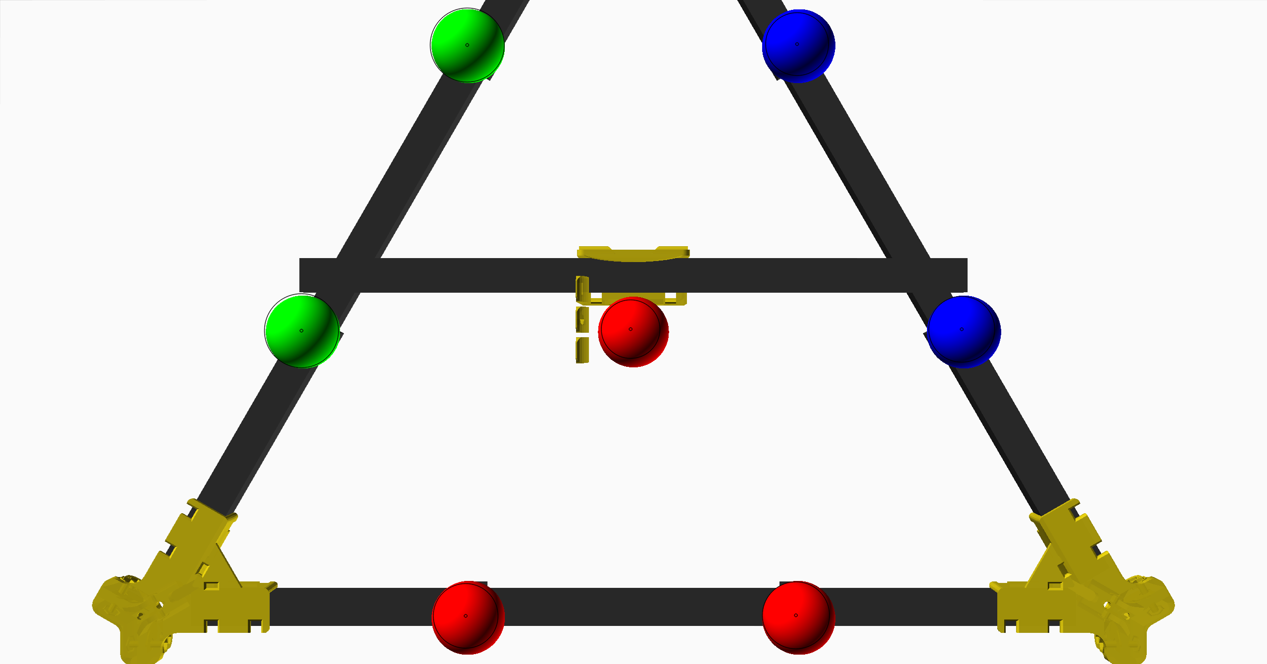
I started with placing out seven spherical markers in OpenScad, and generating some top view images, like this one:
Benchmark image for hp-mark generated within OpenScad.
I generated three top view images,
and the only thing that differentiated them was their different resolutions: 2560x1343, 5120x2686, and 10240x5372.
hp-mark, based on this top view at different resolutions, generated three different sets of position estimations.
I have represented the position estimations with ocean-green spheres in the tilted images below:
Estimations based on 2560x1343 image.Estimations based on 5120x2686 image.Estimations based on 10240x5372 image.
As we see in the above images, position estimations are way off in the camera's depth-direction.
We also see that the error shrinks when the image resolution is increased.
All edge markers are estimated to be closer to the center than they really are, but only by 1mm or less.
The error in the depth-direction accounts for 95% or more of the total error, and it is much worse
on the edge markers.
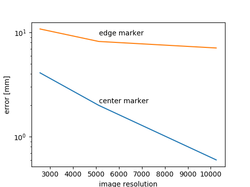
The error of the middle marker's position shrinks from 4.1 to 2.0 to 0.6 over those three images.
The error of one of the edge markers went from 10.8 to 8.2 to 7.1.
Errors on a linear scale.Errors on a semilogy scale.
We see that the center marker's error would probably go towards zero if we continued to increase resolution.
For the edge marker however, the error decreases, but not towards zero, more towards 6.5.
Sooo, hp-mark is probably theoretically right about depth in the center of the image, but
wrong towards the edges.
Something is wrong about how I've modelled the projection then.
While increasing resolution works, increasing the roundness of the spheres (from 70-sided to 700-sided circles)
does not work:
Glare/shadows in very shiny round rendered spheres confuses OpenCV's SimpleBlobDetector, which hp-mark uses to detect circles.
Click on the image to see the failure more clearly.
I guess there is stuff to work on next week as well then. Until then, Bye!
- tobben
Torbjørn Ludvigsen
This is a short update on the previous post.
I've been trying to use OpenScad for generating benchmark images for hp-mark recently.
I produced some learnings that I wanted to publish here.
hp-mark: Computer Vision for Hangprinter
11-11-2020
The hp-mark logo
As promised in the October Newsletter,
I've spent this month trying to add a computer vision system to Hangprinter.
The system is called hp-mark, and is continuously published here.
The core goal of hp-mark is to be able to measure the pose of the Hangprinter effector;
its rotations and translations.
Easy at it might sound, it's quite hard to get right.
Going for developing such a big feature now has changed the direction of HP4's development in large.
Increment or Revolution?
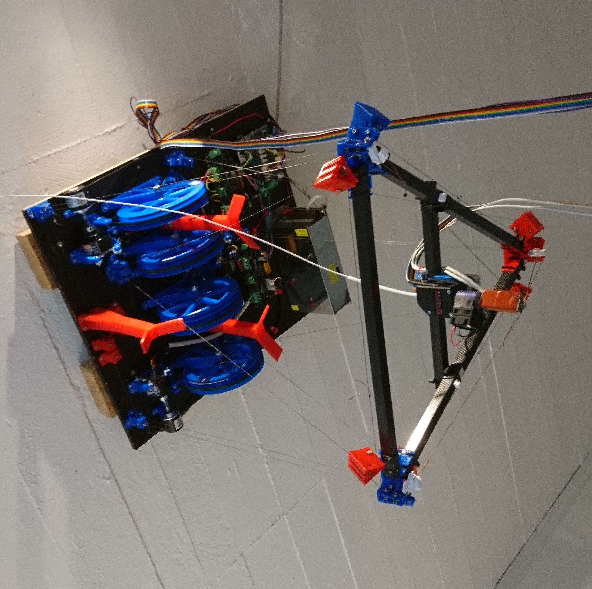
The HP4 Prototype One, the finished and working machine that I mounted in my ceiling two years ago,
is still just a prototype. No official version 4 of the Hangprinter has yet been released.
State of the HP4 PT1 hanging over me as I write this blog post.
The Prototype One can do some nice things, like
printing OK Benchys,
and pushing out
small pieces of furniture.
However, it's still just an incremental improvement over HP3.
It has the same parts and features as HP3, just better.
It also has the same fundamental limitations, just a tad less severe.
It's still hard to calibrate, and lacks precision/accuracy guarantees, just like HP3 did.
So I had a choice.
I could settle on HP4 as an incremental improvement over HP3,
or I could go for the big computer vision feature first.
This is a classical problem of engineering management.
The rule of thumb is to always do the incremental dance, because:
Wrong assumptions get surfaced faster. Saves eons of time and resources.
You'll then always have an up-to-date working machine out there.
Straying Away From Safety
I'm not going incremental, I'm making hp-mark as a from-scratch separate system.
I'll try to face assumptions fast through structured testing in software.
I'll also have to accept that my HP4PT1 machine won't be up-to-date or out there for a while.
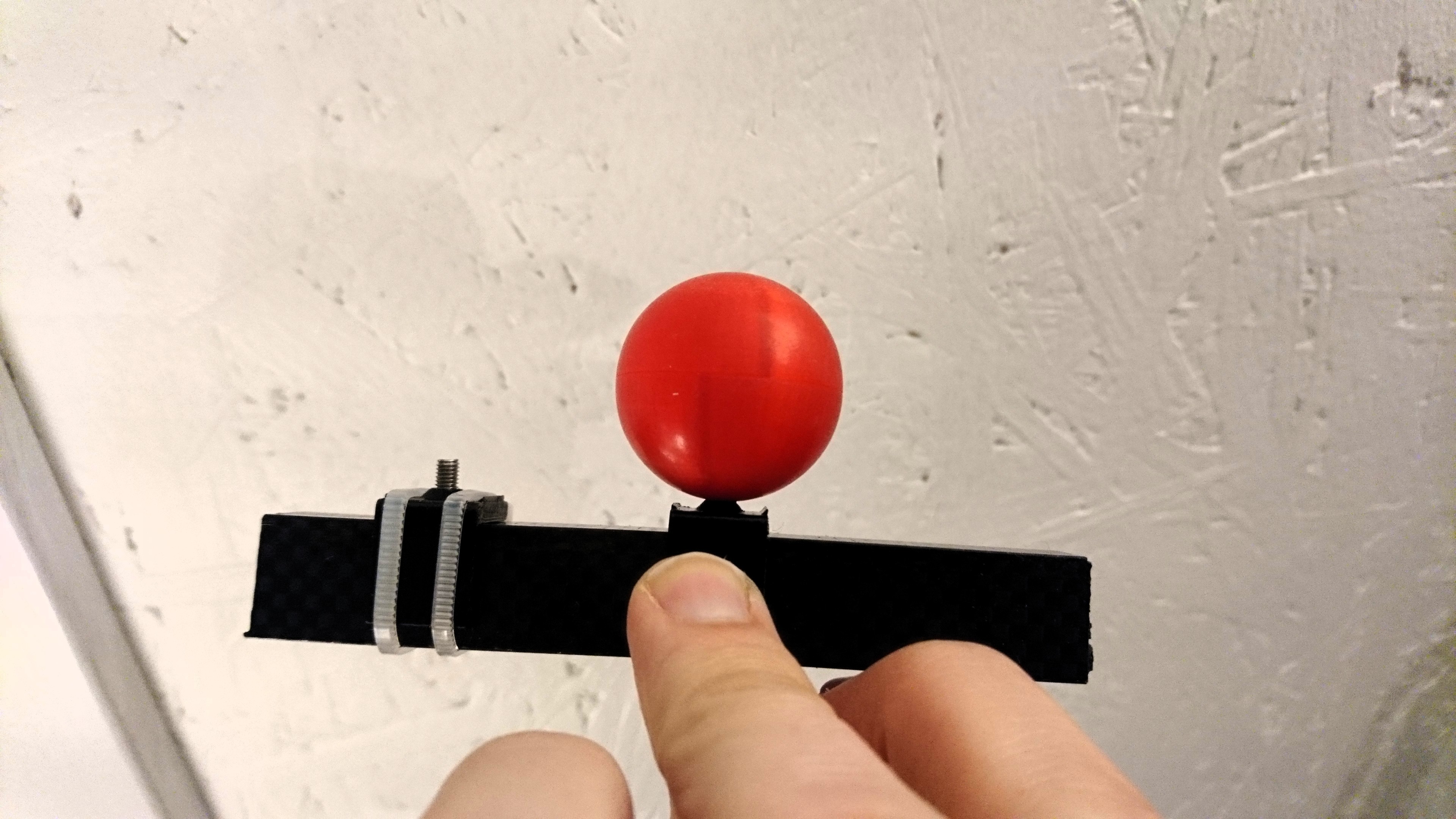
I've also strayed further away from the safe incremental track by deciding to use
colored spheres as markers, instead of the standard flat ones:
Standard flat fiducial marker.
There exist good technical arguments going spherical, but in honesty I discovered those after-the-fact.
My hp-mark decision making process looked more like this:
"I can not use the effector itself as a marker since I want to change it frequently.
So, I must add markers.
The markers must be pretty and practical.
So, effector mountable spheres is my only option."
The currently preferred trade off between pretty and practical.
Development Looks Promising
It has proven feasible to 3D-print small but accurate spheres (with some post processing):
Not too far away from the render, eh?
Libraries like
OpenCV
and
libcamera
work really well on the Raspberry Pi 4.
Support, documentation and tools for Raspberry Pi 4 and the Picam in general
has proven great.
Tools like
raspistill
has given a lot of speed and convenience so far.
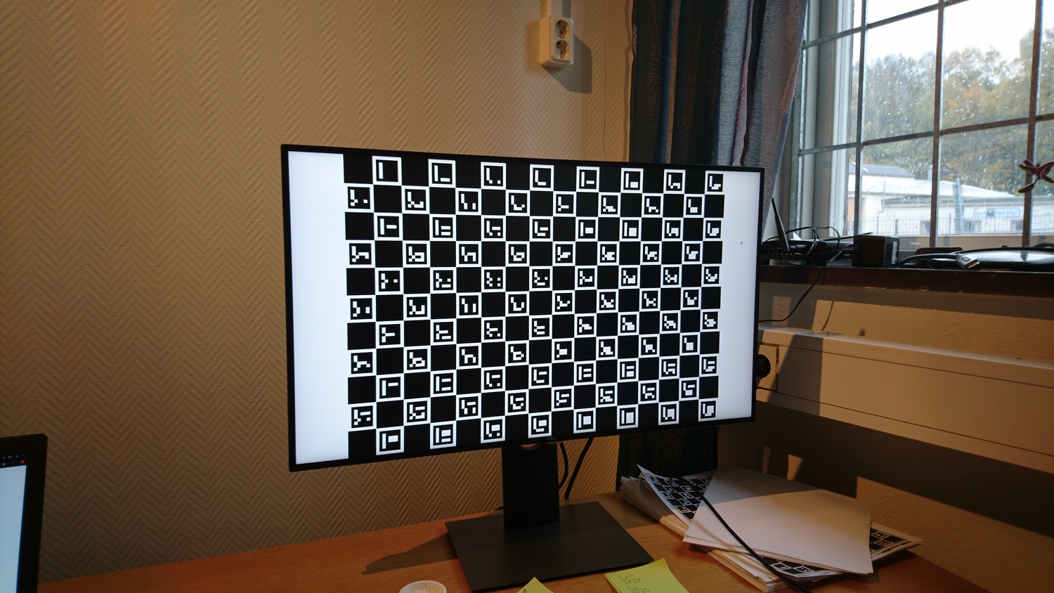
I had to stitch together
a calibration program
from bits and pieces of OpenCV.
It turned out robust enough to work with calibration patterns displayed directly on a flat-ish computer screen.
My monitor during camera calibrationThe calibration program is able to detect my monitor's 0.8mm curvature and compensate for it.
With this calibration, and very simple detector code, hp-mark can already find depth-positions
shorter than 1500mm on real but simple test images with close to 1mm accuracy.
My deck of benchmark images has only 7 real images, so take that 1mm number with a grain of salt for now,
but it sure looks promising to me.
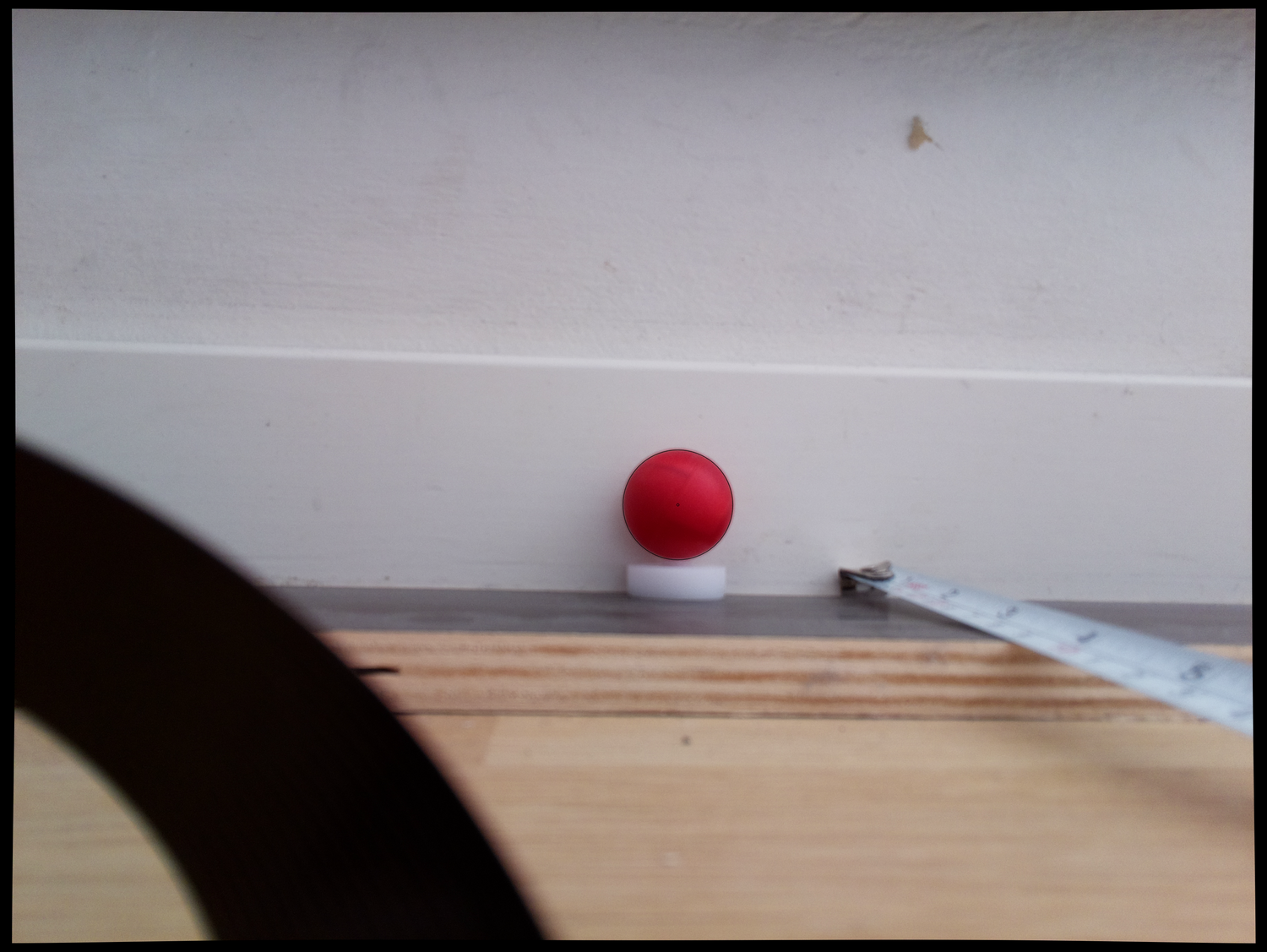
This image is taken only 233mm away from the marker. Click the image or zoom in to see the marker outline and center that
hp-mark has drawn.
The black border stems from undistorting (removing lens-effects from the Picam).
That's the same accuracy as my hand measurements,
so I need a less manual way to generate my next deck of benchmark images.
I've looked into using OpenScad for that purpose.
It could generate benchmark images with known camera- and marker-locations.
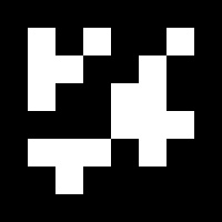
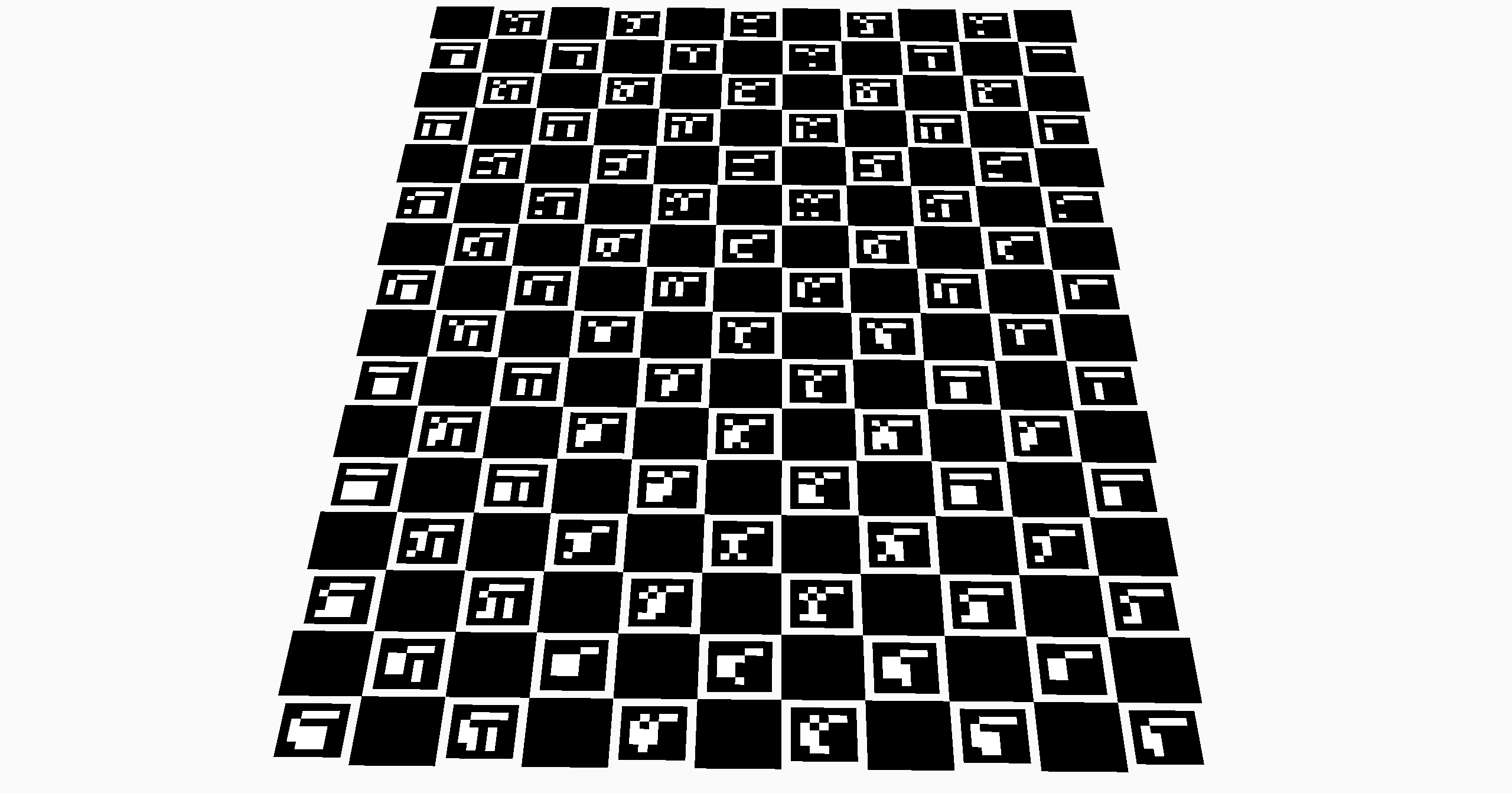
I didn't known the focal distance of the OpenScad camera, so I decided to generate calibration images as well:
Calibration image generated from within OpenScad. Click on image to get full size version.
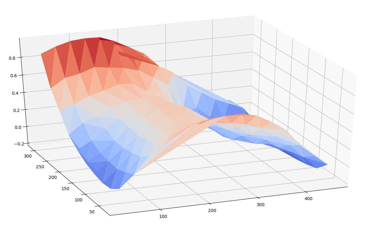
If you look closely at the full size generated calibration image, you'll see that there are no grey pixels,
only black/white ones, and that edges look chopped like a staircase.
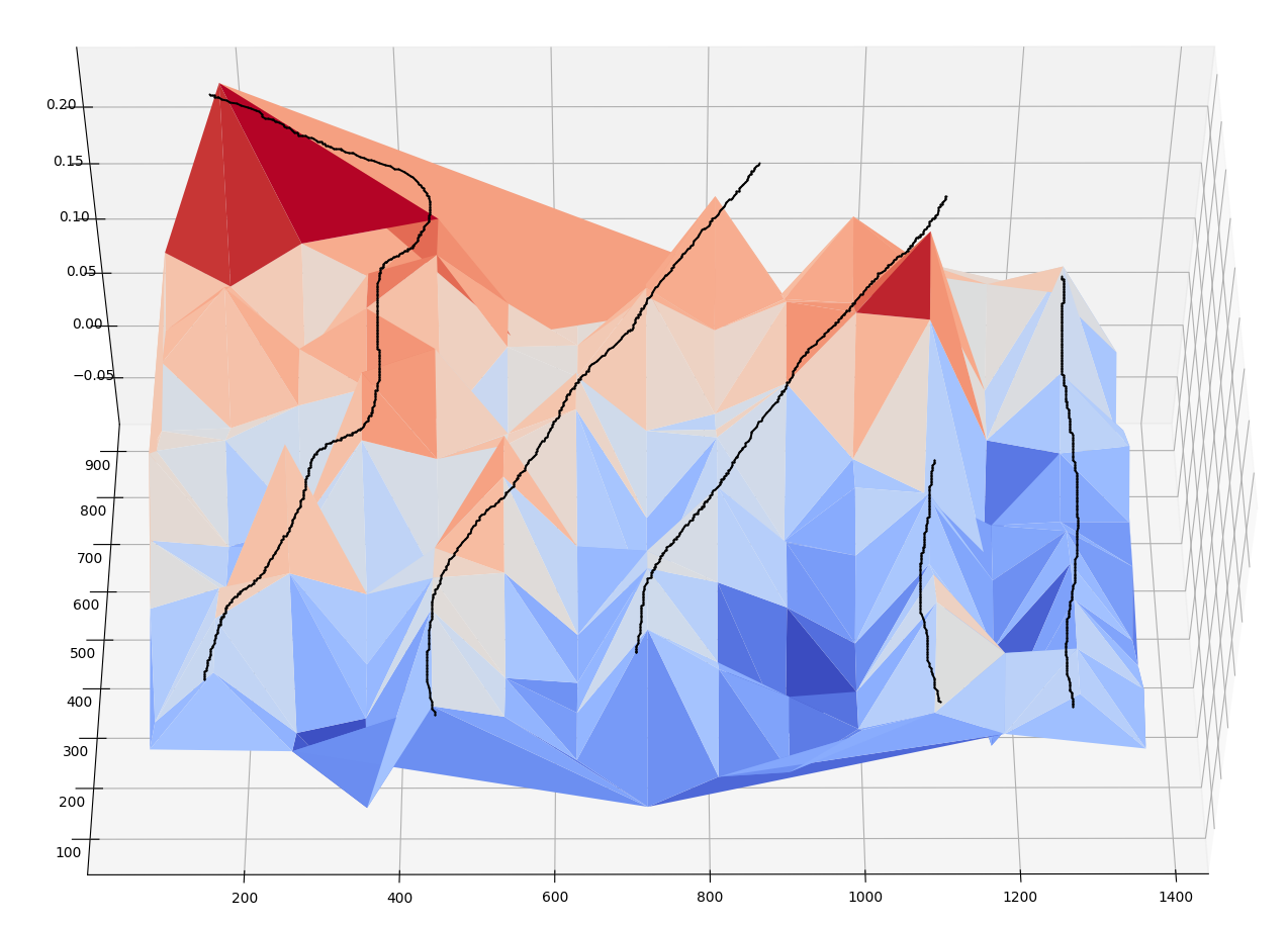
This made my camera calibration program regard the calibration pattern as non-flat:
"Flatness" of the calibration pattern, according to the camera calibration program
after it had analyzed the calibration images generated from within OpenScad.
Click on image to get larger version.
Lines have been drawn in to emphasize the pattern of "ridges" and "valleys" that the calibration program
found that it had to compensate out.
The script that generates the OpenScad calibration images and runs the camera calibration program on them,
(ie how the "flatness" plot above was generated)
can be found
here.
I thought those ridges didn't look promising.
Maybe the calibration program failed?
To check if the calibration program had found the right values,
I carefully deduced the OpenScad camera's focal length by hand.
I managed to do that by generating a large series of images,
and watch exactly when an object enters/disappears from the field of view.
Details about how to do that are here
and
here.
With that very manual trick,
I was able to confirm that the camera calibration program had found the correct focal distance,
within a 0.5 px accuracy.
Anyways, running hp-mark on the pretty and practical image above shows what we want to see:
hp-mark prints out the following positions for the six spheres:
I haven't yet verified that the positions are correct.
All I've done is to be happy that they're so close to symmetrical.
But now it's dinner. Nice to end the working day on a high note. Bye bye.
- tobben
Torbjørn Ludvigsen
As promised in the October Newsletter,
I've spent this month trying to add a computer vision system to Hangprinter.
The system is called hp-mark, and is continuously published here.
This Blog Has Moved To torbjornludvigsen.com/blog
18-9-2020
I'm entering a new period of full-time independent open source work.
I figured that I will need a nice place to publish stuff.
So, I've given my blog some love and moved it to a prettier domain =)=)=).
I have made it easier to maintain, and also added some rudimentary analytics.
(Publicly viewable, see https://torbjornludvigsen.goatcounter.com.)
The new page replaces the good old list of links with more obvious and touch screen friendly navigation.
This is the last post to be published on the old domain, vitana.se/opr3d/tbear.
Ehem. A Few Final Words
It's the end of a little mini-era.
The blog started out in Jan 2014, as a hand-coded html document with 50 lines of hand-coded css.
It wasn't even version controlled.
A friend said "I can host your page", so we uploaded the html, the css, and the images to his server via command-line
ftp.
And it appeared on the web within 1 min, it was a bit magic to me.
My mentality at the time was "keep everything extremely simple, and thresholds extremely low, and feel no prestige ever".
So I kept the ftp deployment strategy, uploading each html and each image individually via command line.
I also kept the long url, added no javascript, no analytics, no comments sections or anything.
There was no platform around it, no ads, almost no readers.
The extreme simplicity and low threshold worked.
It got my productivity from 0 to something.
I wrote simple posts about simple things.
Web programming is very time consuming.
The very simple torbjornludvigsen.com web site took me 10 full working days
to massage into its current shape.
While my old ftp-based hand-coded system was clunky, it has also "just worked" for 6 years straight.
Thanks sluggo setting it up and for hosting it.
I hope the new page will be as simple and robust as what you set up for me in 15 minutes in 2014 :)
- tobben
Torbjørn Ludvigsen
I'm entering a new period of full-time independent open source work.
I figured that I will need a nice place to publish stuff.
Becoming a Type 3 Worker
25-8-2020
I've been thinking about what I want to make this year.
I've quit my job because I wanted to work on Hangprinter.
No real plan. So now what?
I think I will be heading where most of us will be heading.
I think work is changing.
History of Worker Types
Type 0
Let's skip hunter/gatherers.
Let self-sufficient farmers be our basline type 0 workers.
They spent most of their time producing food at home.
A few generations ago, work moved from farms into factories or factory-like workplaces.
They had two pre-defined economical roles built-in, with often conflicting interests, packed tightly together: Workers
and owners.
Theres was some power struggle between them.
Company employment structures were invented to regulate work relations, like families had done for type 0 workers.
Type 1 workers got paid for working hours, so that they could buy stuff during non-work hours.
They became type 1 worker/consumers.
Work and consumption got separate physical spaces:
Work places, and consumption places.
Work and consumption also got separate time slots:
9-5 work, and 5-9 consumption.
This was the happy, but unsustainable equilibrium state worker/consumer type 1:
Producing objects at work, buying objects at home, more and more, better and better.
Type 2
As factories moved abroad, work moved into office buildings.
These produced no physical output.
There was no new power struggle.
Rather, there was a great consensus:
Every single aspect of type 2 economic everyday life
should mimic the type 1 system as closely as possible.
Still more and more, better and better, only not objects.
Workers got employed by companies.
They were paid for being in offices, 9-5.
They consumed 5-9.
The worker and consumers roles were kept distinct.
Words had to change meaning, to make type 1 and type 2 systems fit together.
Words like "work", "consumption", and "employment" were all generalized.
Work became "service".
Consumption became "spending money".
Employer became "shoehorn for legal formalities".
A common way to get "employed" was to create a 1-person company, and simply hire onself.
Most type 2 work was about feeding computers anyways.
It not fit very well into the type 1 system.
Some workers eventually stopped showing up at office.
Instead, they fed computers while travelling.
They called themselves "digital nomads".
They were a hint about what was to come.
Early Type 3
Work soon moved out of offices and onto the Internet.
The Internet was not factory-like or office-like at all.
The consensus about mimicing the type 1 system broke down.
There went 9-5/5-9 time slots, specific work buildings, and employers.
Even monthly salaries went away.
Type 3 workers didn't apply for their Internet work.
They just created content, uploaded to Internet platforms, and waited for users.
No formalities.
Getting paid was more complicated and unpredictible.
Rules and platforms were changing.
Time, size, and even currency of payouts were in flux.
Late Type 3
So here we are, in a new era with less old structure, and with new built-in economic roles:
Platforms, creators, and users.
There is also new finite resource, to spend and earn: Attention.
The meaning of the word "work" is moving towards "whatever someone pays attention to you doing".
Attention now has a fairly predictible exchange rate into hard digital cash, via ads and donations.
Like in the type 1 era, I think we will see power struggles.
Platforms control the attention and write the contracts, without negotiations.
For content creators it's like type 1 work before unions.
Creators need to bond together, and gain the power to refuse bad deals.
Together with users and platforms, they can create fair Internet rules.
This will make platforms better.
My Work
I'm optimistic that platform work will be well regulated.
The platforms are few and exposed.
Creators and users are many and resourceful.
If platforms misbehave too badly, users and creator unions can even make their own.
I've started to think that a type 3 system that works well would be great.
It would nurture the best creators, worldwide and on equal terms.
It would give us more and more, better and better entertainment, science, inventions, ideas, thoughts.
Maybe creators would get paid enough to become first class type 3 consumers, just like type 1 workers became type 1
consumers.
Maybe, just maybe, our thoughts, packaged up like content, will get good enough to solve some of the problems we have
in the world today.
I think I will stop avoiding platforms.
I'm not as scared of them anymore, even if they suck sometimes.
I just have to learn how to use them.
My new goal is to just keep publishing.
Mostly RepRap.
My new value proposition: Giving me money is like watering a flower.
By The Way
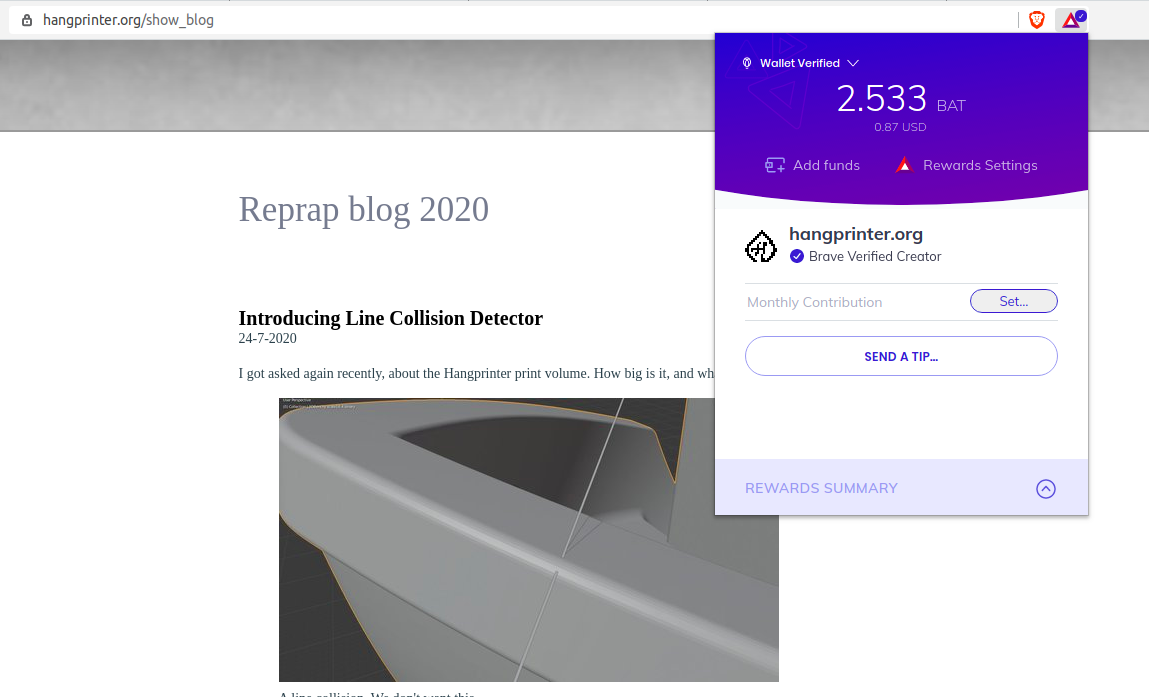
I've found a platform called Brave.
It's a browser that reroutes ad- and content-based revenue streams toward themselves, creators, and users.
It aggressively modifies websites before they're displayed, and has banking built-in.
It might turn out to suck, like other platforms do,
but it might also become what we need to turn attention into creator income via less ads.
It has a list over content owners, and it wants to cover basically all content.
I've registered as the owner of my content, so you can now support me for example like this:
Late type 3 work. You can barely see the human in there anymore. It sits behind the contribution buttons saying "thank you".
Also, if you get Brave Browser via this link, then I'll get a small kickback.
So, hint hint, and thank you for reading.
- tobben
Torbjørn Ludvigsen
I've been thinking about what I want to make this year.
I've quit my job because I wanted to work on Hangprinter.
No real plan. So now what?
Introducing Line Collision Detector
24-7-2020
I got asked again recently, about the Hangprinter print volume.
How big is it, and what shape is it?
A line collision. We don't want this.
A Print Volume?
All 3D printers I know, except Hangprinter, have a print volume:
A volume within which we can print freely,
and outside which we can't print at all.
A print volume has a shape and a size that doesn't change.
The print volume is used to determine if an object is too big for a particular 3D printer.
If the object doesn't fit in the printers print volume, then it is too big.
Otherwise, it's not too big.
The Short Answer
How big is it? What shape is it?
Sorry, can't answer that.
A Hangprinter doesn't have a well defined print volume.
I sometimes lie a bit and say "it's a big trumpet shaped print volume".
That mostly gives a good enough intuition about what's printable with Hangprinter.
And it saves me from having to formulate the long answer.
The Long Answer
Let's first restrict ourselves to objects that are printed layer by layer.
Then, for any particular Hangprinter, assume that we could deduce a max object:
An object that has a larger size than any other object that is printable with that Hangprinter.
Let's call the volume enclosed by the max object the max volume.
It would have the max size and the max shape.
The max shape would probably look vaugely similar to a slightly triangluar trumpet.
Finding it would be nice, and useful.
The max size would roughly capture the size of the entire Hangprinter in one number.
As with a print volume, we could for sure print freely within the max volume.
However, Hangprinter would not be restricted to only ever print within the max volume,
so the max volume would not be the print volume we're looking for.
We'll explain this weird fact, but let's focus on two related, more practical questions first.
What positions are reachable?
What objects are printable?
The Reachable Volume
A hypothetical weightless Hangprinter effector would be able to reach any position within the tetrahedron spanned up
by its four anchors.
Let's call this the enclosing volume.
Adding mass to the effector changes things slightly.
Firstly, the machine then gains the ability to toss the effector out of this tetrahedonal envelope,
so the volume is not an enclosing one anymore.
Secondly, the machine looses the ability to keep the effector still near any of the tetrahedrons three upper faces.
Mass will sag inwards towards the origin, no matter the stiffness of the lines or torque of the motors.
Since Hangprinter can't print out an enclosing volume shaped object, the enclosing volume is not the print volume.
Adding a sag to the enclosing volume gives us the reachable volume:
The volume within which it's possible for the Hangprinter to position its effector and make it stay put.
It would looks like this:
Exactly how much sag to expect can be calculated from the weight of the effector and the maximum static force of the
motors.
Fred Hedenberg made this nice rendering when investigating error due to line flex.
Error due to limited motor power will have the same basic shape.
Can We Print That?
We can't actually reach our whole reachable volume in a controlled way yet, since we don't have flex compensation in
the firmware.
But even ignoring flex, we still wouldn't have been able to print out an object with the shape and size of the reachable
volume.
The problem is, ABC lines point downwards, so they can collide with the half-finished print.
All previously extruded material is potentially an obstacle for every following move.
Every possible half-finished print state shadows out part of the reachable volume in its own unique way.
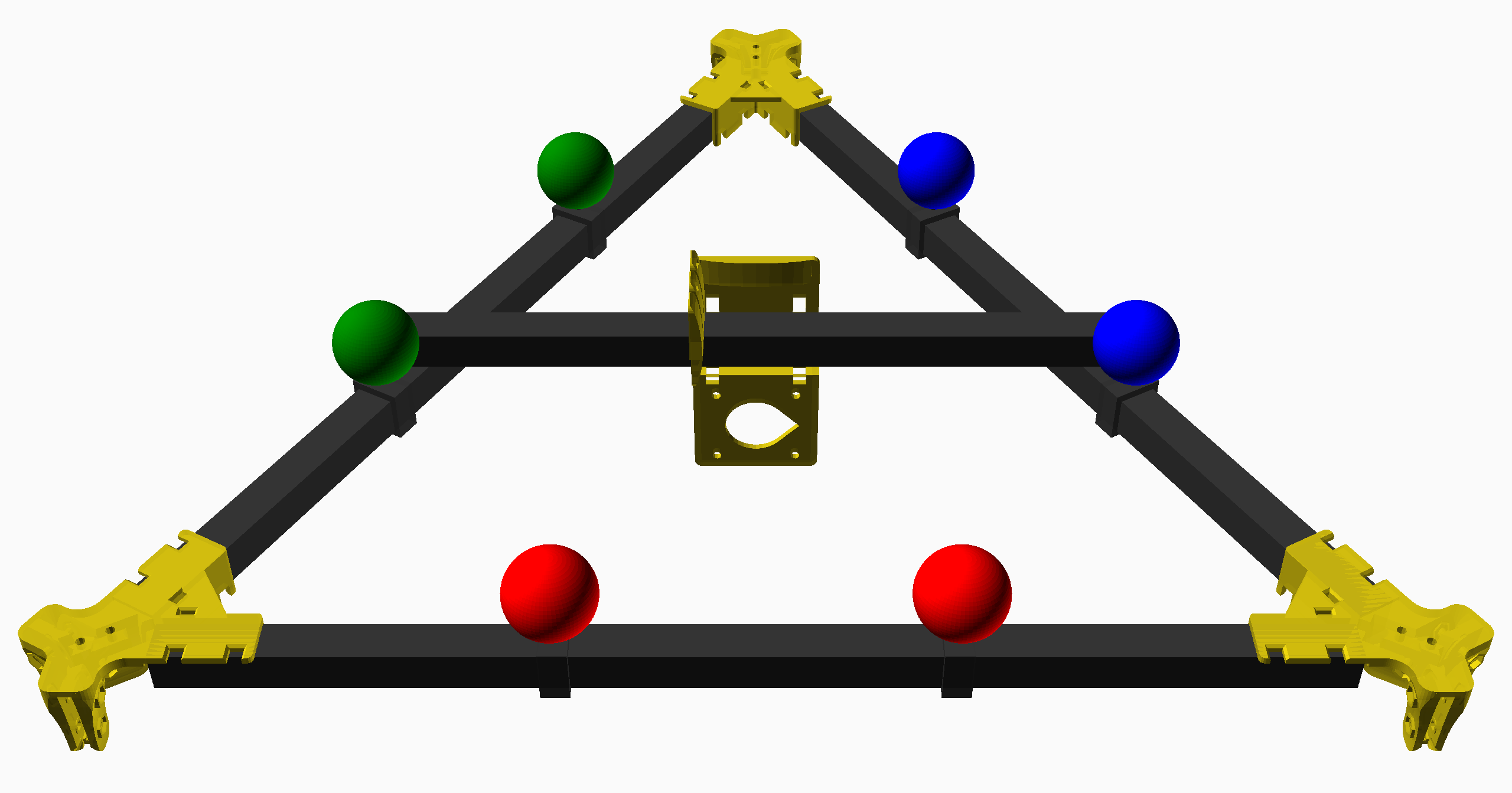
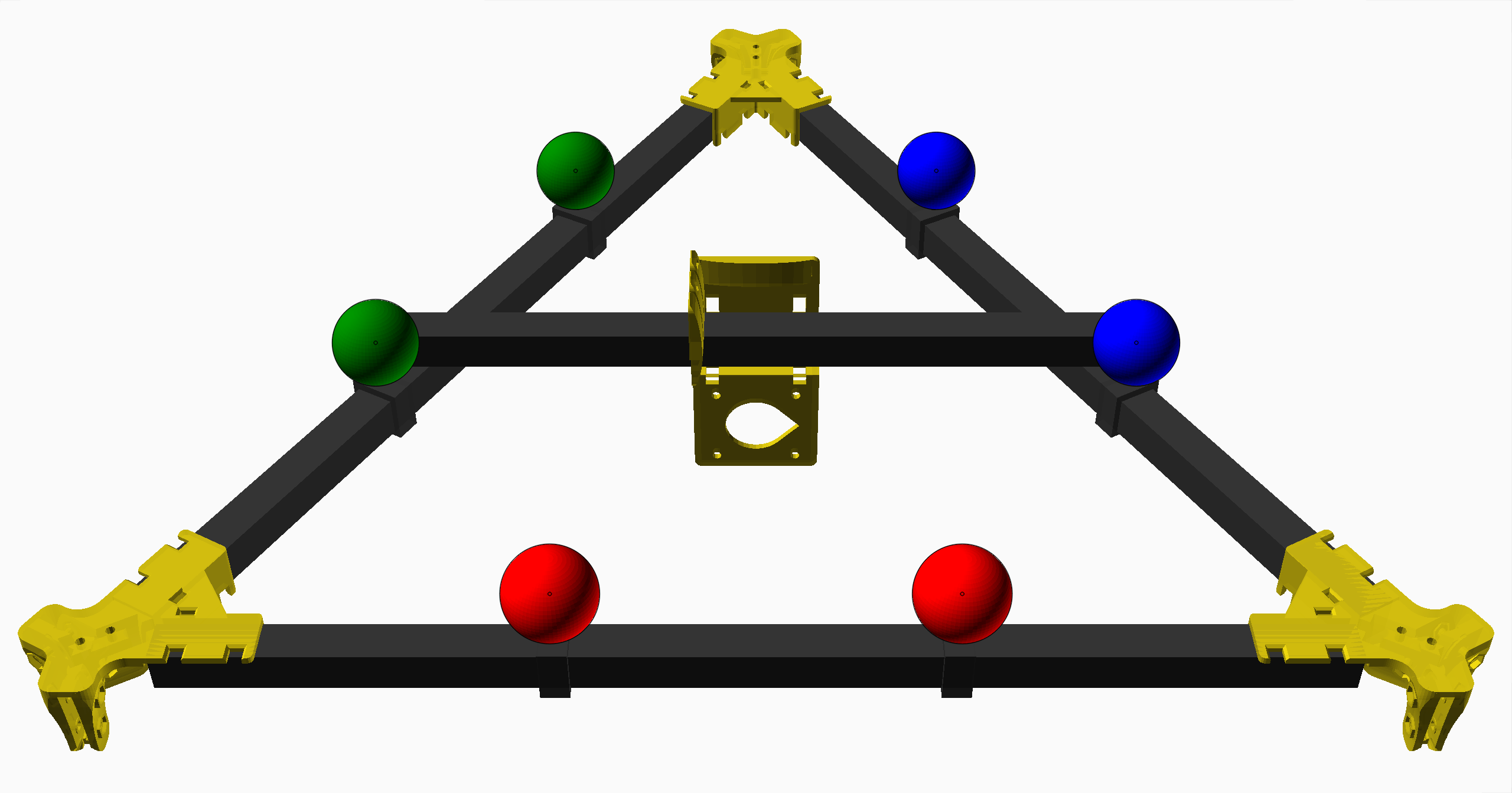
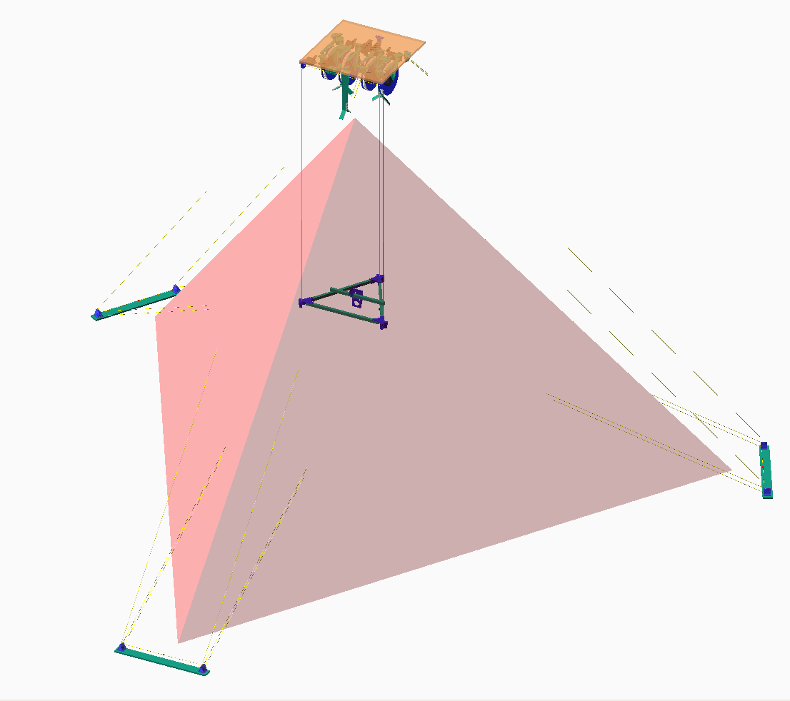
Consider the following render for some intuition about line collisions:
The Hangprinter's effector is attached to the ground with six different lines.
For each layer, each line will move within a "cone shape" (red).
The top of each cone shape is a convex hull of the current top layer.
Line collisions are marked in yellow.
Coming back to the max volume, we can now imagine how it's possible to print outside of it.
We could add a wart on the max object and for every layer, make a render like the above.
Then we could simply remove any part of the old max shape that turned yellow, in order to make the wart fully printable.
Then if the wart turns yellow when any of the later layers are printed, we'll reshape those layers (by creating an inverted
wart
on the appropriate place) until all line collisions are avoided.
That procedure would give us a large printable object that is not contained by the max volume.
Hence we learn that different printable objects might take up different, mutually exclusive parts of the reachable volume.
Ok, so the print volume doesn't exist, because of line collisions.
Let's then revert to talking about printable versus non-printable objects.
No more print volume, only reachable volume and printable/non-printable objects.
What Can We Print Then?
For every object that we want to print, we must perform a separate
analysis to check whether a line collision would occur.
The result of the analysis, depends on a lot of things, like:
The positions of the anchors,
the shape of the effector,
how the object is rotated,
where it's placed on the build plate,
where we make our travel moves,
and in which order we put down the material!
Lots of stuff to think about, and for every single print.
Sounds like we're in trouble?
The Solution
As complicated as the analysis sounds, it shouldn't have to be more than a small addition
to the wealth of analyses that common slicer software already does for us before every single print.
We as users should get a warning if a potential line collision is detected.
The rest of the time, we shouldn't have to think about line collisions at all.
Detecting line collisions isn't entirely trivial, but I'm happy to tell you that it's already done =D
It's not baked into any slicer yet, but I've written a free-standing program who does the analysis separately.
Let me present line-collision-detector.
The most basic usage of line-collision-detector.
A collision is detected.
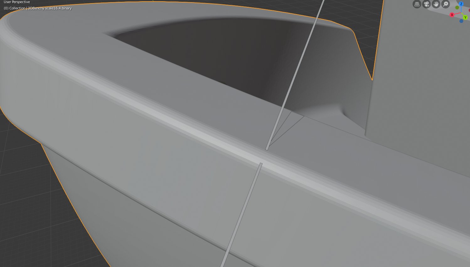
The big-benchy.stl contains a 16.4x scaled up benchy.
The params file contains positions of anchor points and effector pivot points.
See the params-example
file in the repo for information about the params file.
Here, a non-scaled 3DBenchy is analyzed, and since it's so small, no collision is detected.
The -l option is used to tell line-collision-detector to use a layer height of max 3 mm.
A bigger l-value lets the program terminate faster because there are fewer layers to analyze.
I recommend viewing this in fullscreen.
Here, the -o option is used to create a debug model, which is inspected with Blender.
We can confirm that the effector is at a sensible position, and that there really is a line collision occuring at
z=393.6.
This post is already quite long, so I realize I should save the details of the line-collision-detector
algorithm for another blog post.
Anyways, I hope you find this new tool useful!
And well, I now kind of have a better short answer to "how big is the build volume?":
Ca one 15.675x scale 3DBenchy =D
EDIT: Oskar on the Discord server discovered the largest print volume that's always safe, an called it "Hexatrumpet".
This enables a new way to guarantee that lines won't collide: just keep the model inside the Hexatrumpet.
No Hexatrumpet has been modelled yet as of Dec 2024. But we found the basic maths: See Discord discussion about Hexatrumpet.
- tobben
Torbjørn Ludvigsen
I got asked again recently, about the Hangprinter print volume.
How big is it, and what shape is it?
Everything on this homepage, except those videos who are published via Vimeo or Youtube, is licensed under the Gnu Free Documentation License.
The videos published via Vimeo or Youtube are also licensed via Vimeo or Youtube.


