Prior Art Relevant to Patent US 11230032
The patent in question was filed on April 13, 2018. We will refer to the patented contraption as SkyBAAM, or "the patented contraption". We will present prior art relevant to SkyBAAM, all of which were unmentioned and unreferenced in the patent. We find most of our prior art examples within the open source project called Hangprinter.
The patent contains many ideas that have been explored, published, and then discontinued within the Hangprinter community before April 13, 2018.
This writing will be long and detailed. The corpus of relevant prior art published publicly before April 13, 2018, is vast since the Hangprinter Project was already four years old at the time. This prior art includes, but is not limited to:
- 56 technical blog posts: [1], [2], [3], [4], [5], [6], [7], [8], [9], [10], [11], [12], [13], [14], [15], [16], [17], [18], [19], [20], [21], [22], [23], [24], [25], [26], [27], [28], [29], [30], [31], [32], [33], [34], [35], [36], [37], [38], [39], [40], [41], [42], [43], [44], [45], [46], [47], [48], [49], [50], [51], [52], [53], [54], [55], [56]
- Ca 350 posts on Reprap forums
- A few hundred posts in the Facebook group
- Ca 25 relevant Youtube videos
- 37 videos published on Vimeo
- Ca 100 Tweets
- 13 Hangprinter Newsletters
- Wiki articles on Appropedia, Open Source Ecology and Reprap Wiki.
- The hangprinter.org landing page
- A public Github repo containing over 500 relevant commits and issues
- A number of news articles, including but not limited to these
- An unreferenced Russian Patent (not Hangprinter)
- A widely known cable-driven robotics project called on site robotics (not Hangprinter)
- Three other unreferenced robots that are similar to SkyBAAM both in name and workings:
- SkyDelta (not Hangprinter)
- Sky Printer (not Hangprinter)
- SkyCam (not Hangprinter)
Hangprinter References In the Patent
The patent made two references to Hangprinter:
- The English Wikipedia article, which was mostly just a list of links at the time
- An out of date article from 3ders.org
Those two sources alone do not cover enough details to reveal how deeply similar SkyBAAM is to the pre-existing Hangprinter. I will therefore present a selection of prior art here, picked from the long list above.
I will comment on prior art covering the highest level, most general ideas presented in the patent first, and slowly zoom in on technical details and implementation. However, some similarities are visible at a distance, without further explanation. I will cover those first.
Complete Concept From A Distance
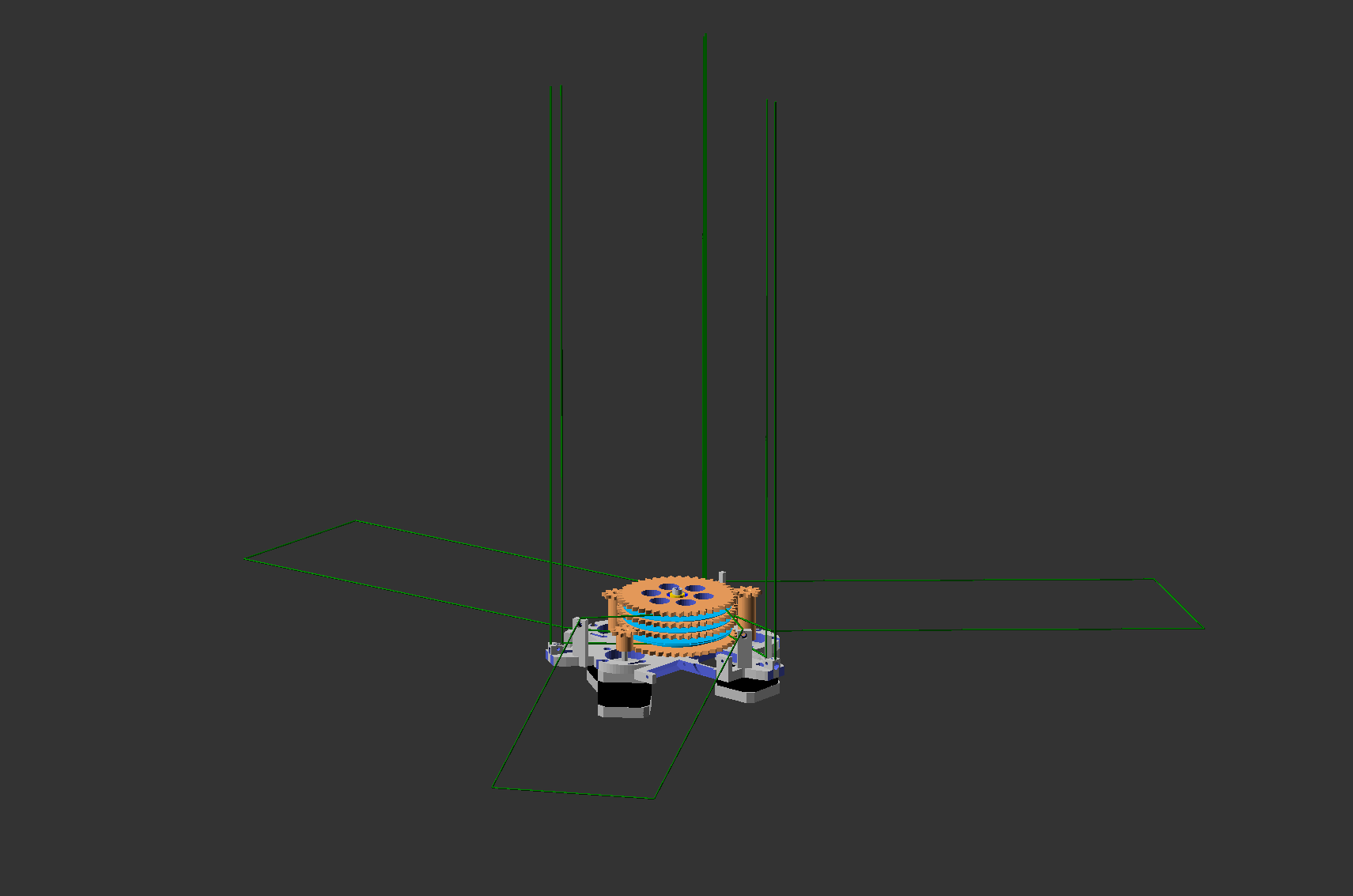
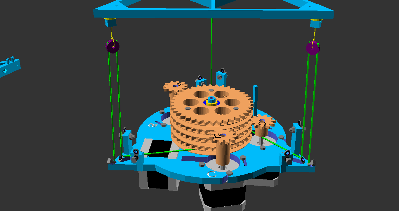
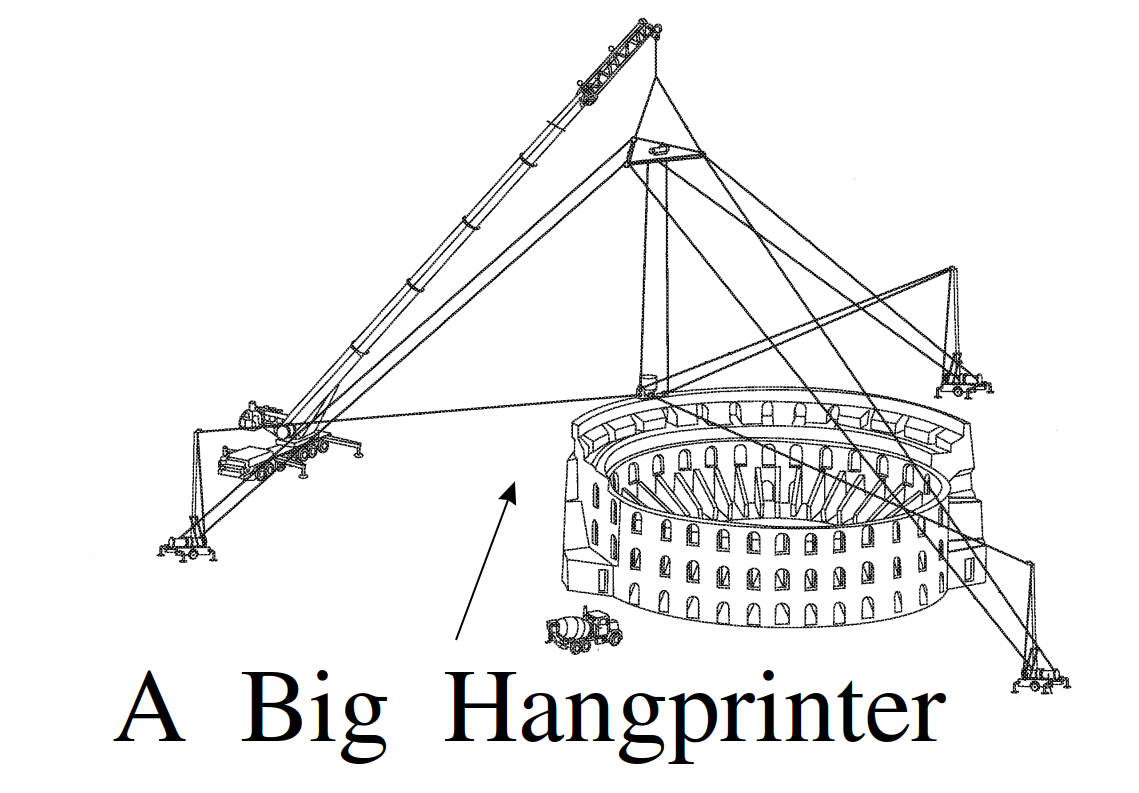
The first thing that strikes you is how Fig 2 from the patent in question looks like a feature-by-feature copy of the most widely published press images of Hangprinter from 2017.
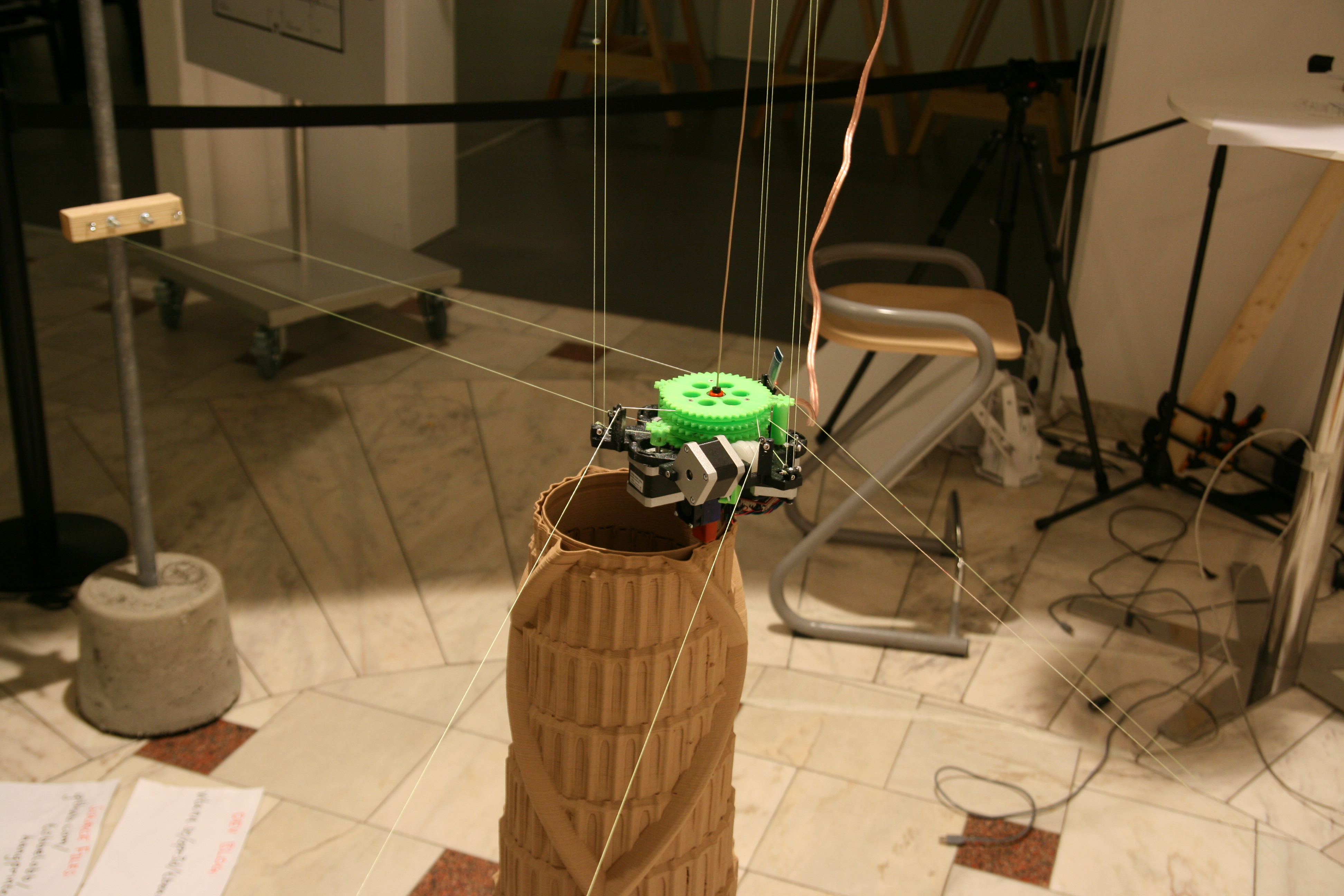
The artistic expression (as well as the physical implementation) of:
- an open circular structure with tall arched windows,
- a thick helical structure along the outer wall,
- being 3d printed,
- by a cable-driven parallel robot,
- with four cable directions,
- one of which is near vertical,
- and an end effector with rotational degrees of freedom constrained,
- by pairs of generally parallel cables,
- of which anchors are potentially lifted above ground level,
- by thin, tall structures,
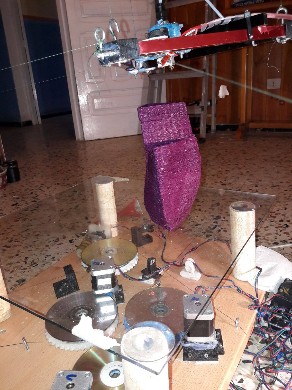
Images of the Hangprinter printing a Babel Tower were published on every 3d printing news site in March 2017, including but not limited to:
Look Closer, And Similarities Continue To Appear
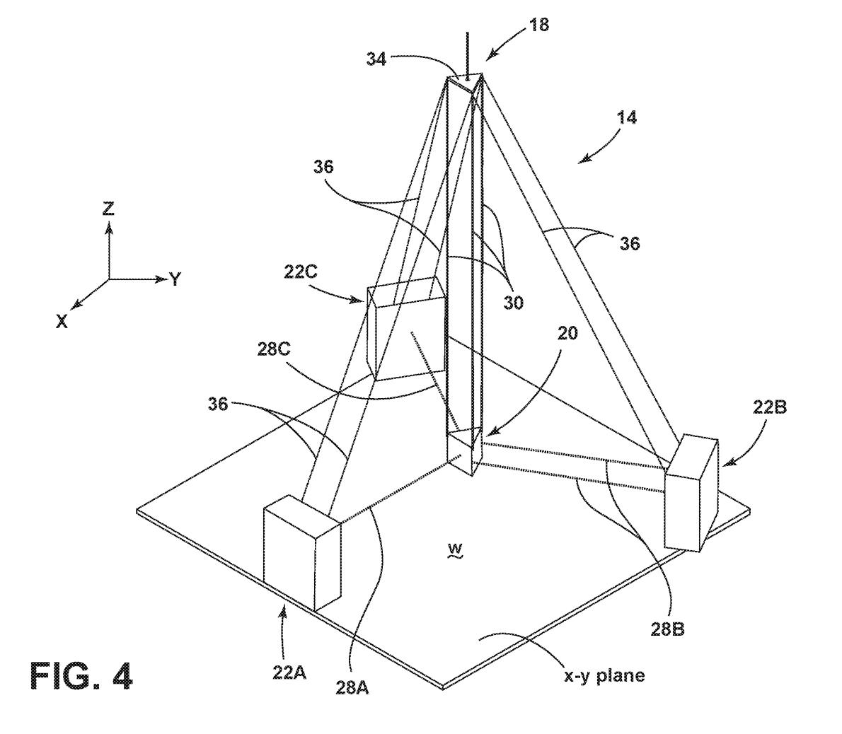
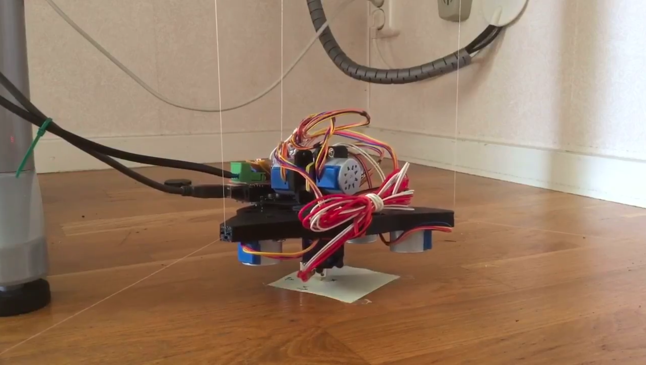
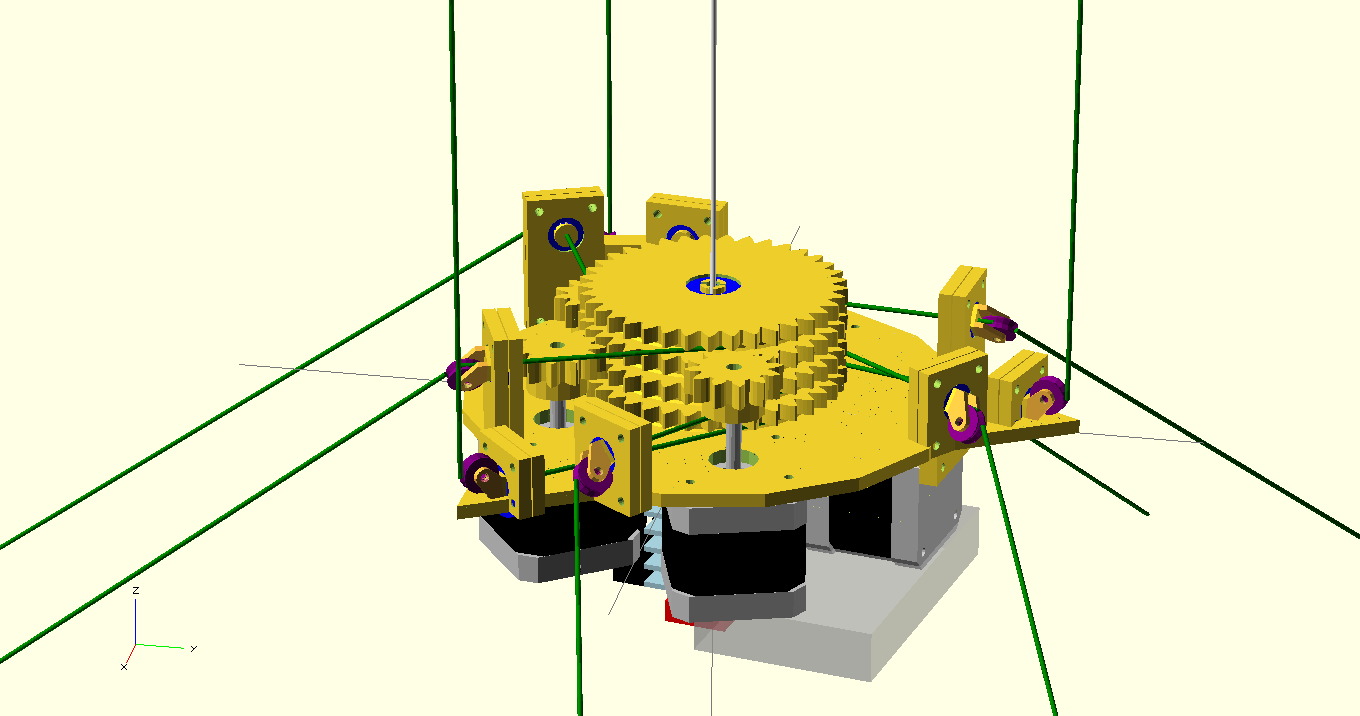
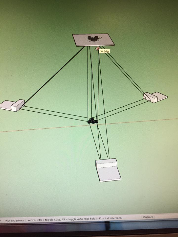
The Hangprinter most visually similar to Fig 4 might be a early version 3 prototype published and explained in the Facebook group on April 23, 2017. The same prototype was also described in some detail in a blog post on April 4, 2017.
The patent seems very broad. I might have misunderstood it because it's hard to read. Let's try to read it closely.
So What Does The Patent In Question Cover?
I tried to understand the claims section of the patent. As an engineer, I must say, the claims section reads like someone is preparing for a post-modernistic poetry slam competition.
From reading only the claims, it sounds like the patent tries to cover the field of translational parallel cable-driven robotics in its entirety, or a very significant portion of it as if it didn't already exist.
Any Number Of Lines And Base Stations
Formulations like these in the detailed description give a similar, overly general impression:
- "[...] an outdoor work site. Smaller-scale and/or indoor implementation are also contemplated"
- "one or more additional base stations"
- "one or more additional adjustable cables may be associated with any of the base stations"
- " the base stations 22A, 22B, 22C can include at least one pulley 42, multiple pulleys, or another suitable cable guide which route the cables 28A, 28B, 28C to change the direction of the force applied by the cables"
Maybe the rest of us will have to continue our research on machines with three or fewer base stations, then?
Hangprinter's Number of Anchors
As we will see later, in the firmware section, adding one anchor does not increase the computational complexity of the kinematics. The option of adding more motors and anchors was being taken care of and discussed publicly before April 13, 2018.
It was also widely understood in the Hangprinter community that we sooner or later would want to add more anchors to Hangprinter.
That was easy to understand because many translational parallel cable-driven robots with similar goals as ours already had more than four anchors a long time before April 13, 2018, thereby reaching larger volumes and better performance overall.
Hangprinter's Number of Lines
The most common configuration in 2017-2018 was to have 2/4 lines in ABC-directions, and 3/6 lines in the D direction, like this:
However, we experimented with 1 and 3 lines in the ABC-directions and 1 (possibly doubled line) in the D-direction.

A Hangprinter remix dubbed "Hangaround" by Jonas Forsell, May 28, 2017, used the single-ABC-triple-D configuration shown above.
Its rotations around the z-axis were completely unconstrained, a property it could have in common with the contraption on Fig 2 in the patent if the two attachment points or the 28B are stacked vertically. Therefore, these machines' end effectors oscillate like a torsion pendulum (not prior art) during operation.
We even experimented with using suspended closed loop belts instead of cable winder spools so that we could tie in any number of lines to the belt at any time, like this:

We kept the D-line a single one (or "doubled up" however you see it).
It turned out that if the D-line attachment point was singular, then the end effector needed three attachment points in all the ABC-directions to constrain its rotations properly. I repost the video here to save you from scrolling back.
The number of anchors and lines in a parallel cable-driven robot is quite fluid and easily adjustable. Specifying a set of fixed numbers or saying "one or more" does not constitute an invention in the field.
Anyways, let's see if something in this patent might still be valid.
Probably Mistaken Descriptions Of SkyBAAM's Motion System
If we read the patent more closely, it turns out that the patent's claim 1 and the detailed description narrow the scope down considerably if taken literally.
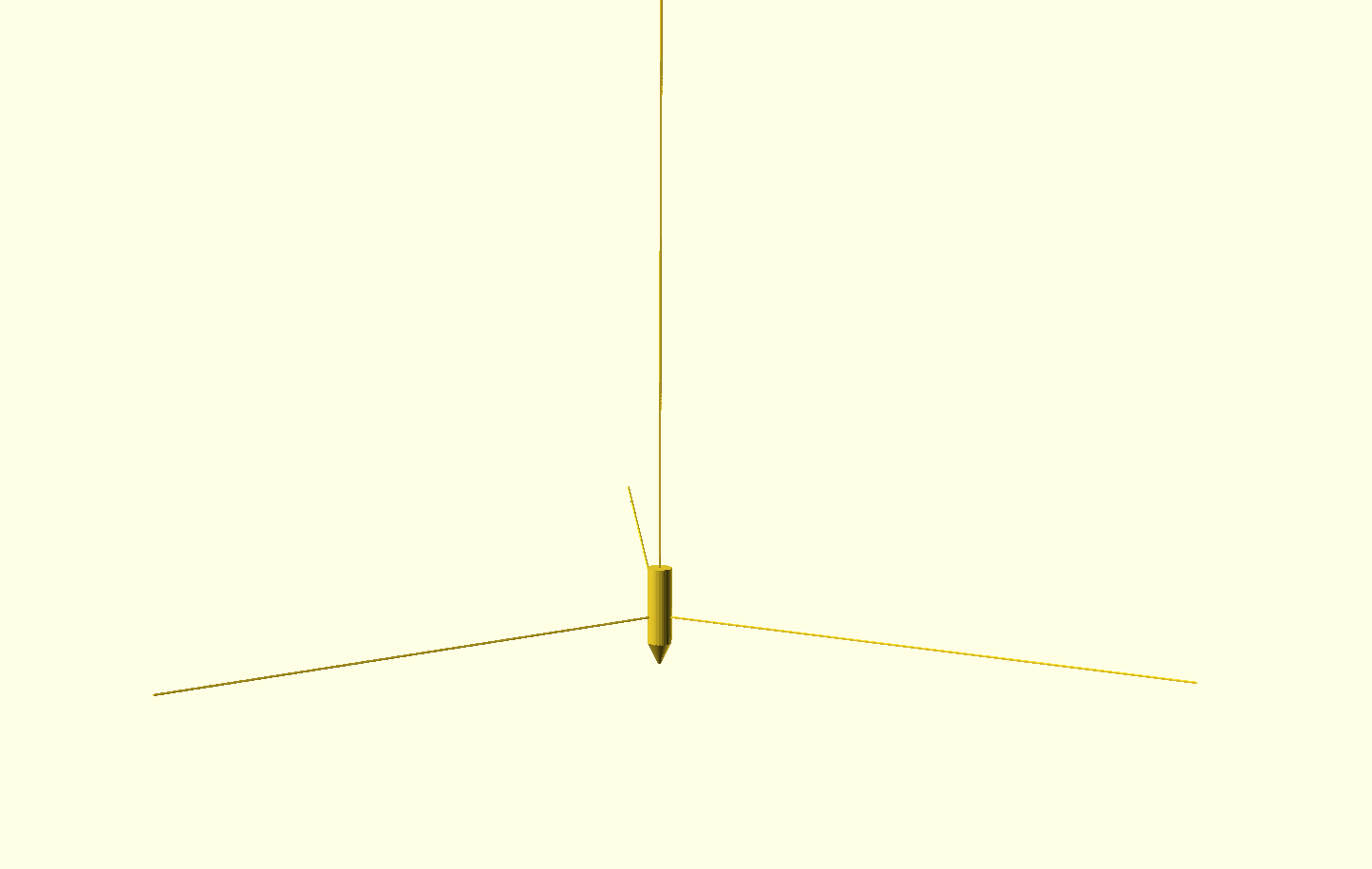
A stationary end effector is described in several places. Maybe they are all mistakes. I will explain.
"FIG 4. [...] three adjustable suspension cables 30 run from the aerial hoist 18 to the end effector 20, and perform the z-axis motion"
Since "the fixed platform 34" is stationary, the formulation "z-axis motion" indicates that the end effector 20 can only move along a straight vertical line. Like this:
Movements "along the z-axis" and movements "towards the highest anchor" are generally not the same in a Hangprinter type of robot. They are only the same if the end effector is situated directly below the highest anchor and moves in a straight line towards or away from the highest anchor (given that the z-axis of the machine is vertical, which the patent text states clearly elsewhere).
The statement that the hoist "controls linear translation along the z-axis" or is "at least a portion extending along the z-axis" is repeated eight times in the patent, including in claim 1.
In a Hangprinter type of robot, all the cable-driven movement axes are involved in controlling any linear motion of the end effector. If you want to move along a straight line, you must adjust the length of all the cables connected to the end effector. No anchor, not even the highest one, has any particular relation to either of the x, y, or z-axes of the Cartesian coordinate system.
That understanding makes the patent's description of the movement system sound very narrow, bordering on the unexpected. Let's help the patent authors by assuming they made a mistake.
After all, Fig 4 is only "another embodiment of a cable configuration for the cable-driven additive manufacturing system". So let's look closer for details that differentiate it from Hangprinters and other embodiments.
Descriptions of Angles and Constraints In The Patent Text Are Wrong
"One difference is that three adjustable suspension cables 30 run from the aerial hoist 18 to the end effector 20 [...] all run off one cable winder 32 [...] so that their length is always identical."
I think they mean this, or in video format:
"This keeps the end effector 20 from tilting, which freezes two rotational DOF of the end effector 20."
I'm unsure what "freezing" means here since degrees of freedom are independent of degrees of temperature. Ok, let's assume they made a mistake again. They surely mean "constrains two rotational DOF", right? Like this:
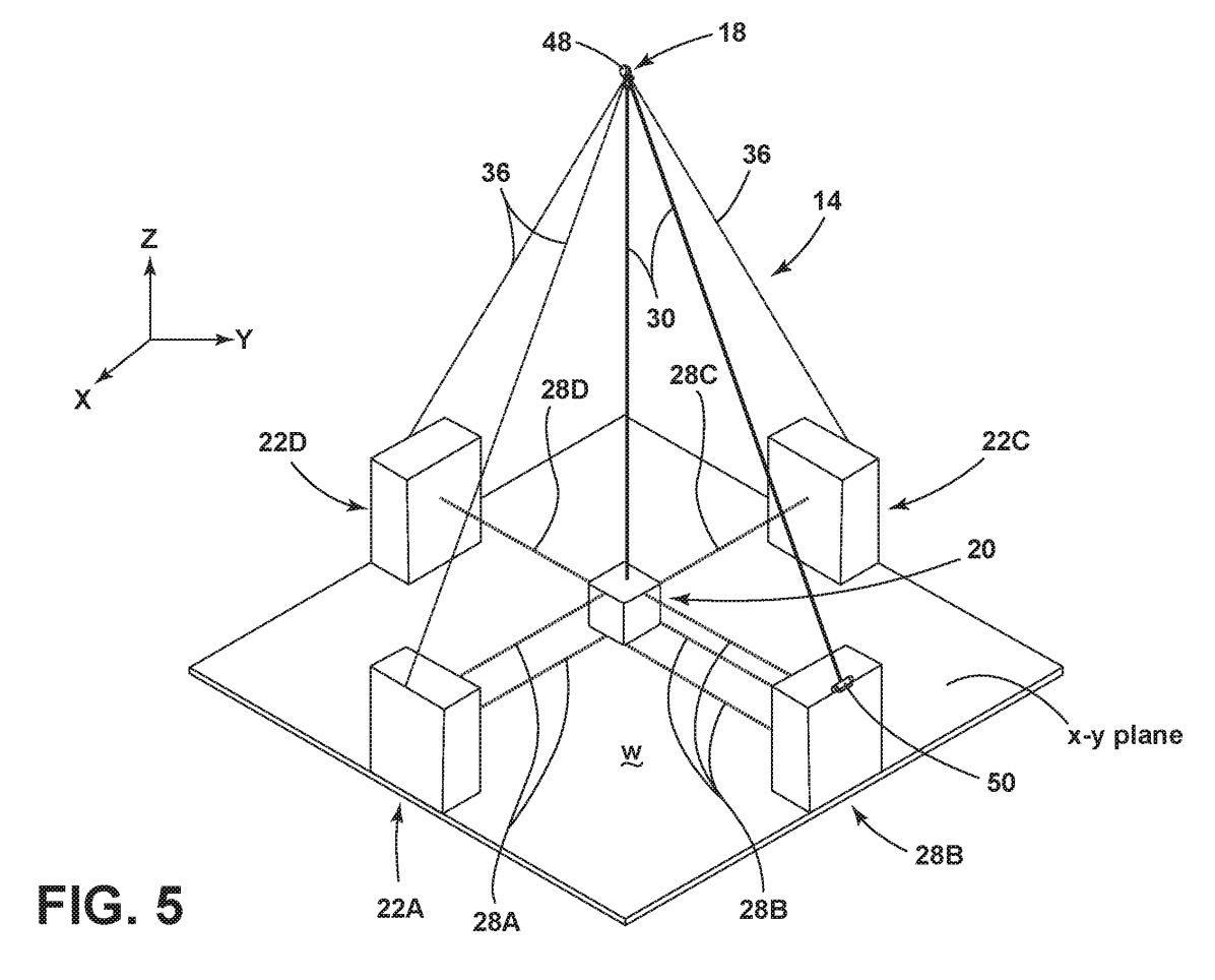
Even if they meant "constrained", they would still be in error. Those rotational degrees of freedom are not constrained in either of their Figs 4 or 5. That's because they specify that all cables, and hence anchors are in the x-y plane:
"... freezes all the rotational DOF [...]. First, by putting more cables in the x-y plane, the stiffness of the system 14 is increased in the x-y plane."
In claim 1 of the claims section, and ca ten other places in the patent text, the patent authors insist on base stations being the ones who control motions in the x-y plane specifically:
"motion-control base stations disposed below the aerial hoist and configured to control linear translation of the end effector in an x-y plane defined by the x-axis and the y-axis".
That is the same mistake as with the "z-axis" above. In reality, all lines are extended or shortened during any linear movement, and base stations can not be constrained to only control motions in an x-y plane unless all of the machine's moves are in that exact plane.
One section of the detailed description in the patent tells us more about what the authors intended to describe. They want to allow the lower cables to tilt up to 20 degrees (upwards?) during operation: "... or alternatively up to 20 degrees from parallel to the x-y plane during operation."
But that's probably not enough either. In reality, these angles get steep quickly when the end effector moves close to an anchor (base station).
These angles will not be "substantially in the x-y plane" or any other fixed plane.
Last Geometry Nitpick, I Promise
I'm trying to assume that they're honestly trying to describe regular translational 3d movements as other translational cable-driven parallel robots do, but the patent's authors don't make it easy for me:
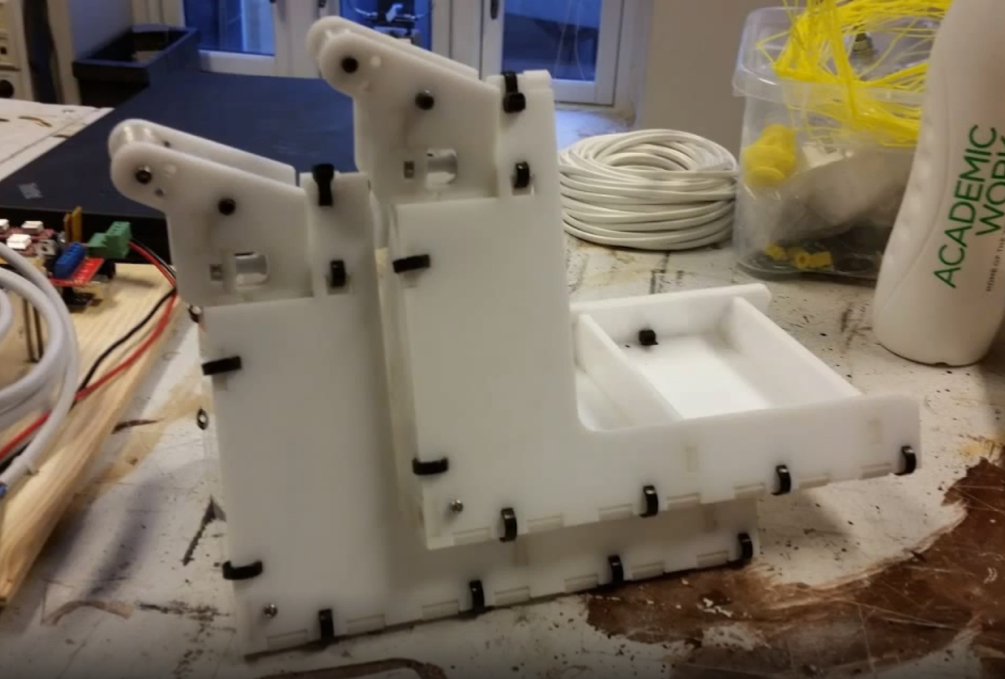
"From the pulleys 42U, 42M, and 42L to the end effector, the cables 28U, 28L can run generally orthogonally to the support surface 60."
The number 60 they're talking about is the front plate of this thing:
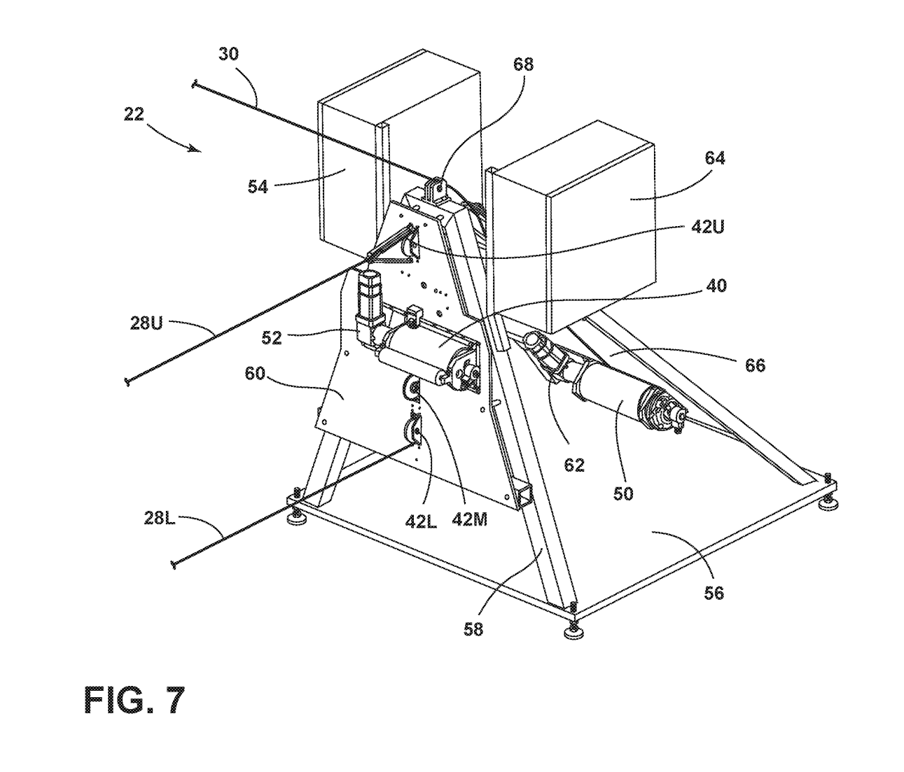
So, if the cables 28U and 28L are orthogonal to the front plate 60, the end effector can only move along a parallel line to plate 60's normal direction. With three different normal directions, this again constrains the end effector to stay put at a single point in space (or probably at no point in space, if we're going full-on mathematical about it).
In reality, the lines 28U and 28L will not stay orthogonal to 60, not even close, not even "generally".
Let's assume the patent's authors made another mistake. We wouldn't want the patent authors to have patented this very general situation inadvertently:
Telescoping Framework: For More Substantially Horizontal Lines
The patent authors get back on track by specifying:
"In one embodiment, at least a portion of the base station 22 can telescope to raise the pulleys 42U, 42M, and 42L."
So we're back up to one embodiment of their patented contraption that can carry out linear vertical motions by utilizing a total of at least seven motors.
The telescopes are supposed to act like linear vertical axes that can lift the pivot points of the lower lines. We can see that in Fig 2, or look at earlier Hangprinter implementations of the same thing:
So the idea of lifting Hangprinters anchor points during a print was something we practiced before the patent's filing date.
Moving the anchor points' positions around required pausing and resuming the print in the video above. Avoiding the pause/resume cycle by motorizing this linear movement and potentially making it continuous should be considered an obvious idea for scaling up a Hangprinter.
We will get back to the firmware details later in this text. Let's first look at how SkyBAAM planned to do it:
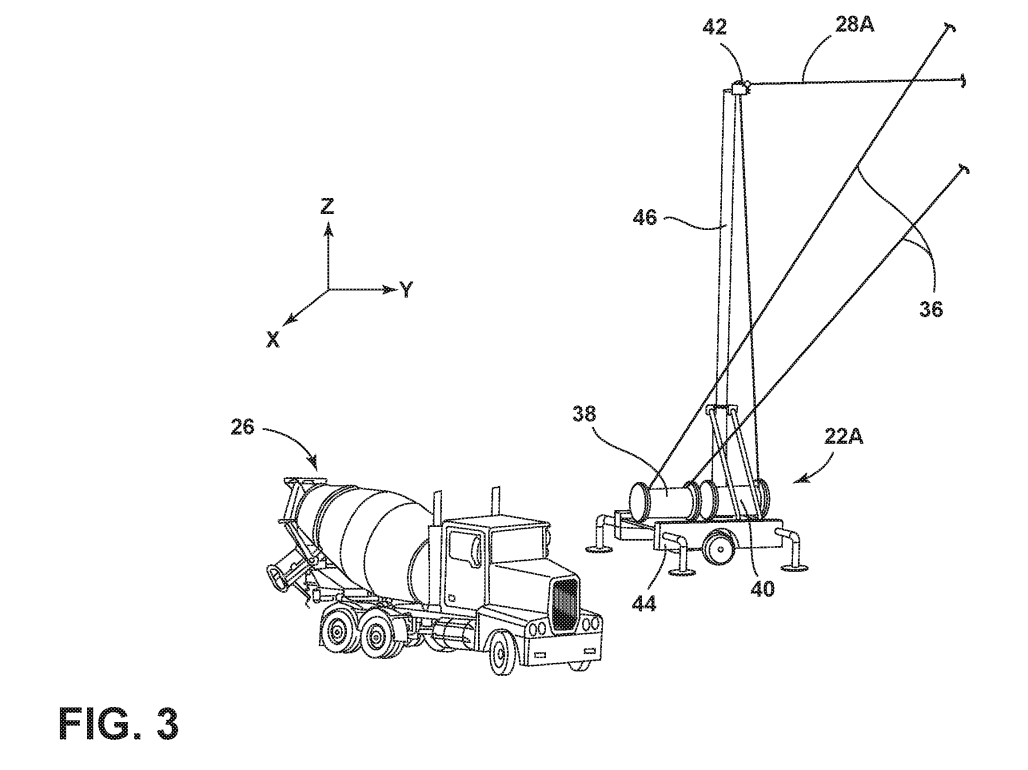
I am a bit amused by the base station thing with wheels to the right in fig 3. Have they invented a kind of mobile crane, restricted it to purely vertical crane motion, and removed all but one pair of wheels? Also, instead of anchoring the guy wires to the ground, they anchor the guy wires to the little truck.
Oh well. Just don't pull too hard in 28A, and wear a helmet, alright? The weight of the sagging suspension wire 28A in itself could be enough to make base station 22A fall over on its side, particularly on a windy day. See Appendix for better ideas.
But SkyBAAM Has An Aerial Hoist! Hangprinter Sources Never Mention Aerial Hoist!
Yes, the patent authors have invented their own jargon to describe their cable-driven robot idea. That's cute but also a bit confusing. Let's look closer at the "aerial hoist".
"The base station 22 can optionally include a cable winder 50 for a suspension cable 30 used to adjust the position of an aerial hoist 18 (FIG. 8)."
Let's look at Fig 8 and Fig 2.
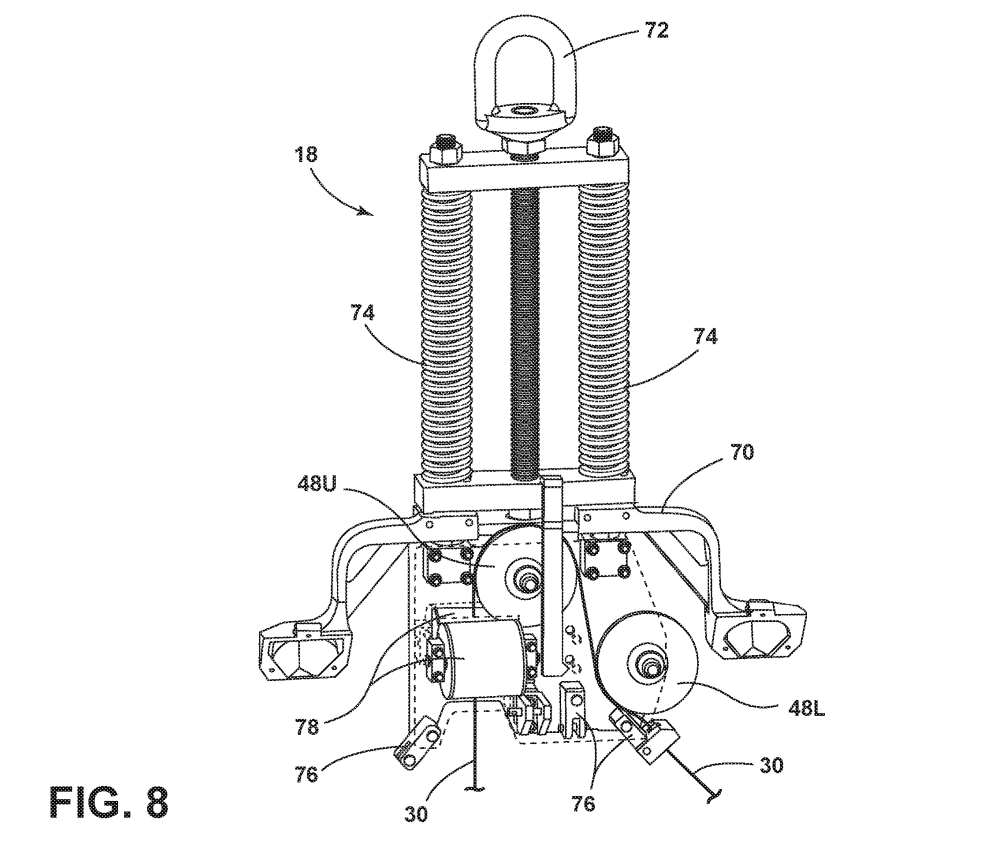
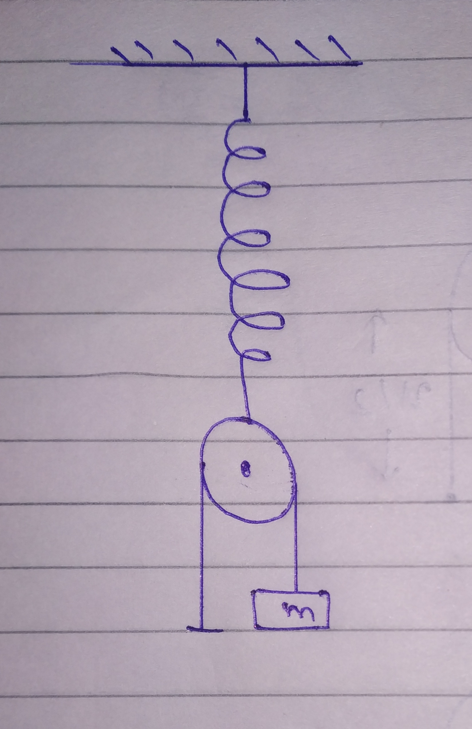
After some deep reading of the patent, it turns out that the aerial hoist is a spring-connected pulley, just like the ones used in common homework problems in introductory mechanics courses.
The springs (nr 74 in Fig 8) have the same effect as flexibility in the suspension cable. Since the UHMWPE lines of Hangprinter already provide more flex than we need, we've never attached explicit springs to our machines. We'll come back to the explicit spring later in this text.
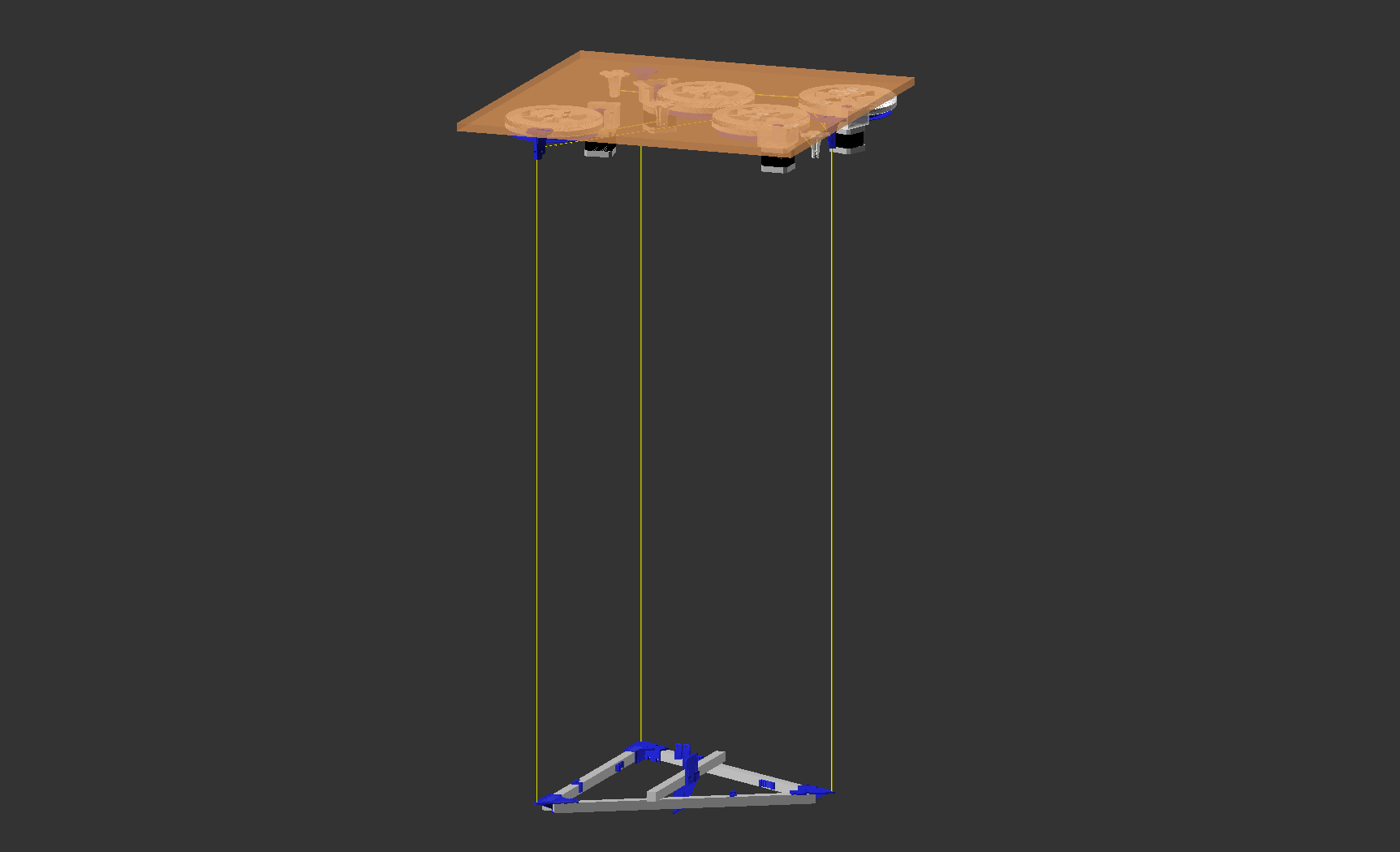
So, the "aerial hoist" does the same job as the v-shaped bearings in this image (except Hangprinter avoids springs if it can):
However, the "aerial hoist" in Fig 8 "in one embodiment" redirects the line towards an anchor ("base station"), so that all motors can potentially be located at ground level. Once again, we can look at Hangprinter prior art to explain what they mean.
SkyBAAM's aerial hoist also redirects the cable, one could say. But Common cable blocks redirect all cables of all cable-driven robots in practice. Motor placement on a cable-driven robot is entirely arbitrary because cable redirection is cheap and straightforward.
If the "invention" of the patent in question is the concept of routing lines through elaborate cable guides, fairleads, or blocks, then let's consider these very early sketches as prior art:
But SkyBAAM Adds Springs! More Cleverer Than Hangprinter, No?
It's true that Fig 8 includes explicit springs (74) between the top hook and the cables and that Hangprinters don't have this.
Introducing springs here and there to keep lines tight or avoid over-tightening is a common beginner's mistake when designing Hangprinters because it reduces positional control, limits maximum speeds and accelerations, and introduces eigenfrequencies in the motion system. Adding springs to Hangprinter has been discussed many times. We don't add springs because there is already more than enough flex in its UHMWPE lines.
However, earlier open source translational cable-driven parallel robots did use explicit springs, like for example, this one:
The way forward for all Hangprinters, from Mini to SkyBAAM size, is to handle, and possibly plan for, the flex and springiness in the lines (or in the actual springs, if you add them voluntarily as SkyBAAM does). Some related theoretical work was published on my blog on February 21, 2018.
But How About Houses, Scaling Up, Using Concrete, Using A Crane For the Top Anchor?
Questions about scaling up and using concrete were answered many places in 2017, for example an interview on Thomas Sanladerer's Youtube channel, March 30, 2017.
To be clear, the original Tower of Babel myth does not describe a 40x40x460 cm tower made of plastic. The artistic idea was to make the audience imagine something huge, dwarfing the Colosseum.

Printing buildings with Hangprinter was on my mind before the Babel Print Project, and I tried to make that evident by choosing the Tower of Babel as my motive.
Anyways, the idea of printing with cement appeared already on the first page of the first forum thread about Hangprinter back in 2014 and has kept appearing at a rate of every fiftieth forum post or so suggesting it. My reply has always been "go for it", and it should be straightforward.
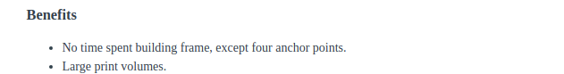
Scaling up is among the first two benefits I mention in the first blog post about Hangprinter, from May 15, 2014.
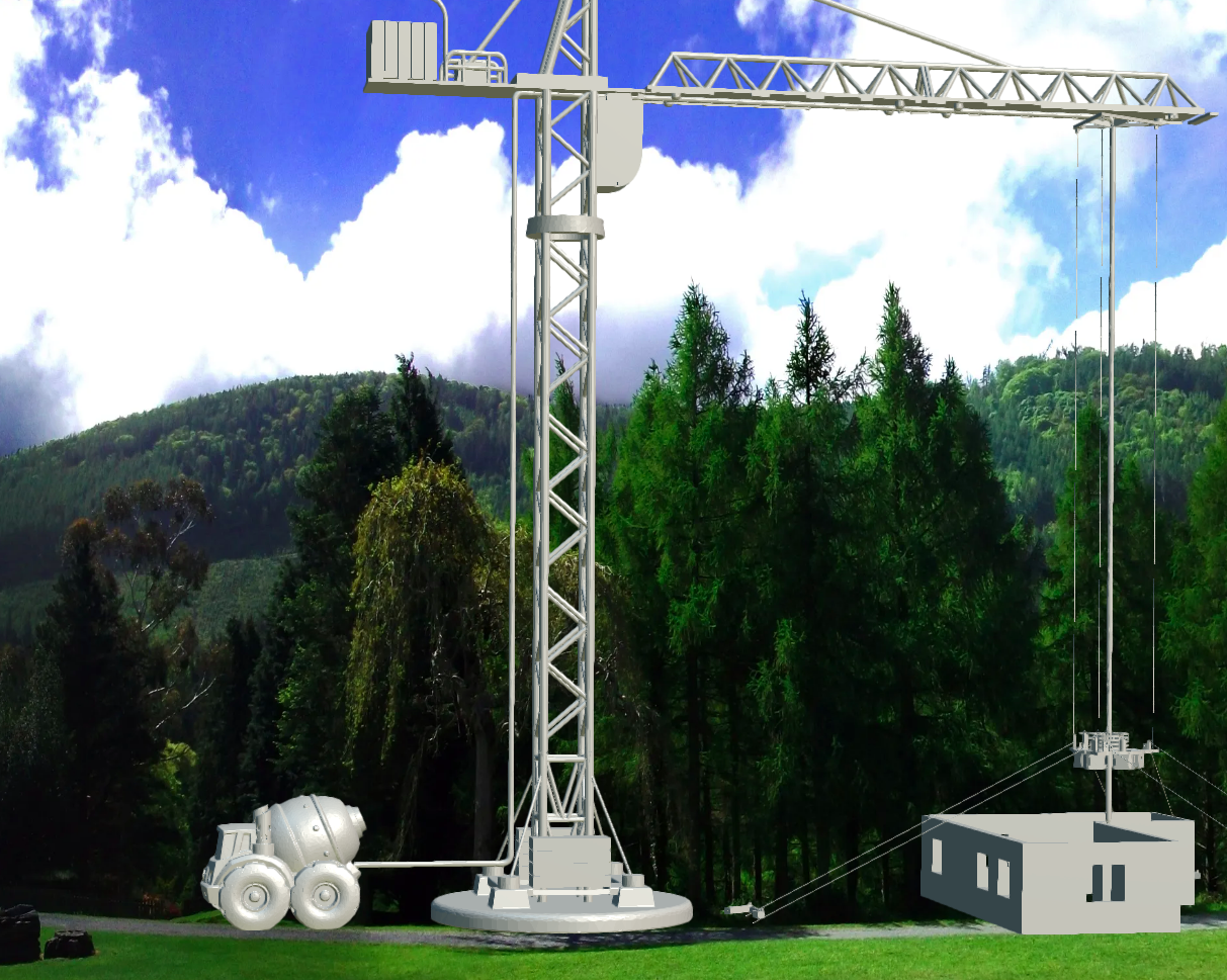
Apart from being very obvious and being the first explicitly suggested idea in the official Hangprinter documentation at the time, the general idea of "3d printing houses with Hangprinters, out of concrete, hanging from a crane", like industrial scale, was frequently discussed in public between 2014 and 2018. One of the more entertaining conversations included these visuals.
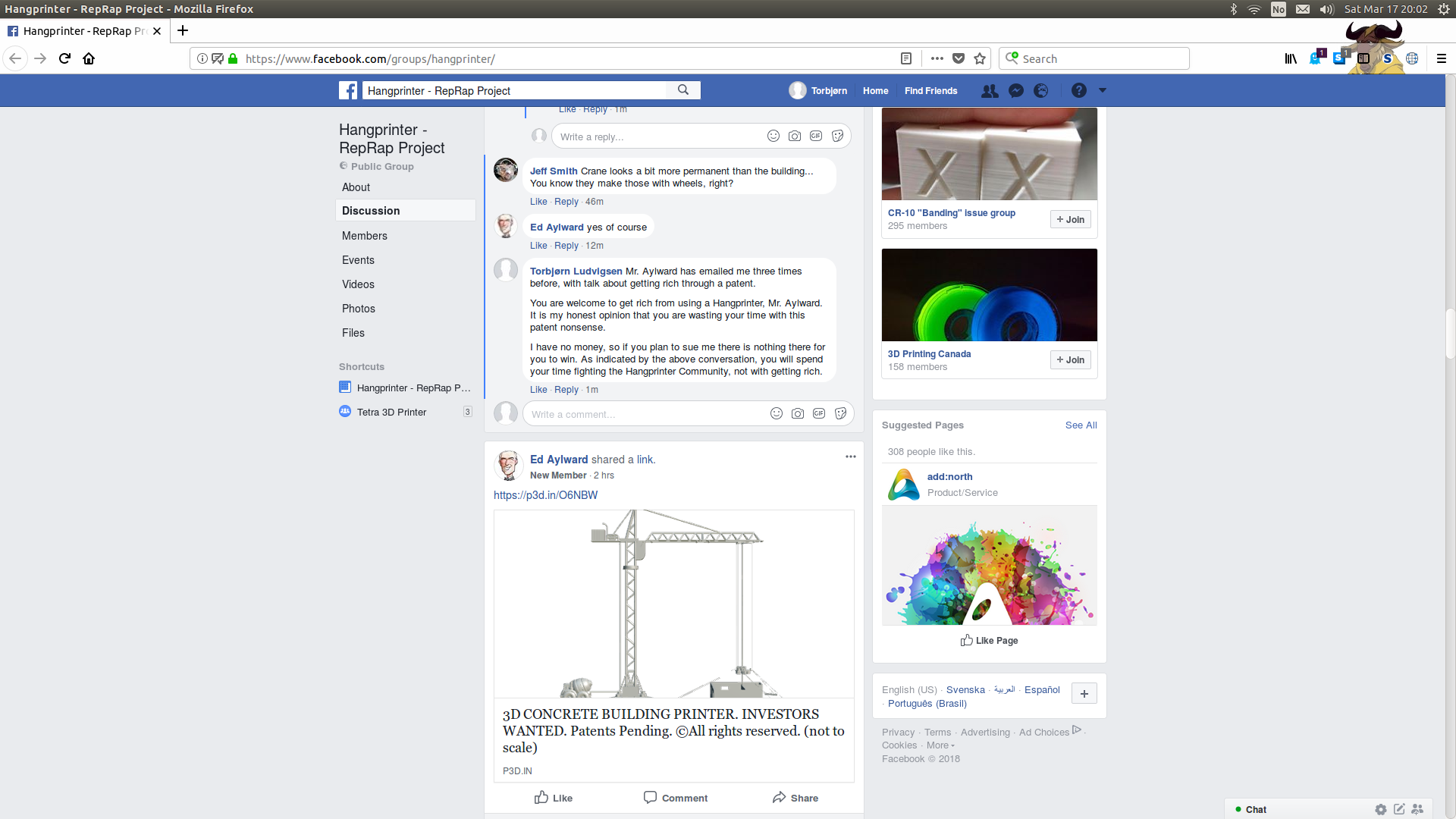
The group had over 200 members and increased rapidly, already a year earlier. It was a big and rapidly growing public group with active discussions about Hangprinter, open for anyone to see, including non-members.
Wayback Machine saved the web page that Aylward linked to in his post on February 28, 2018. At the time of writing this, Aylward's web page is still up.
Initially, however, it was unclear whether the "invention" in these visuals was to
- Scale up a toy mixer truck, or to
- scale down the idea of a crane.
Luckily, Aylward included an object of known size in his 3d visualization:
The image would imply that the "invention" was a combination of the two above. A colossal toy mixer truck, pushing a cylinder down through a standard Hangprinter via a tiny crane.
Ok, I am just kidding. The "print houses" idea is obvious, even in Aylward's posts.
But The Super Smart Tension Control Described In the Patent, How About That?
In the Hangprinter Community, we call it "torque mode". All Hangprinter anchors have this tension control.
Torque mode has been a standard feature since 2017. It's convenient and lets you start the printer up and move the end effector safely and rapidly without overthinking. Usage during printing is possible but uncommon.
Torque mode is also used during auto-calibration (automatic anchor localization within the Cartesian coordinate system). During auto-calibration, it's common for a Hangprinter to mix the normal "position mode" with torque mode, frequently switching modes for individual motors.
A non-linear minimization algorithm is applied to transform the set of collected quadruples of motor positions, into four anchor locations. The algorithm version available on April 13, 2018, can be found here: auto-calibration-simulation-for-hangprinter.
This video from September 4, 2017, shows how automated data collection looks in practice:
Fun fact: the precursor to Hangprinter's torque mode was called "button mode". Mikael Tulldahl invented it, and I published it on my blog on June 4, 2017. It looked like this:
If the somewhat vague tension control concept in the patent involves measuring the tension along the line, that's ok. We've done that as well.
But SkyBAAM Has Its Cable Rewinders At The Base Stations! Hangprinter Does Not
Placing motors and spools at the anchors is another discussion that has kept coming back at a rate of ca one out of fifty forum posts. The following one is from February 2017:
- MechaBits: "Was there a reason you never went with the motors on the walls?"
- tobben: "Yup several reasons, of course. One of them is that I have to tidy up after me each time I've used the printer. [part of quote left out for brevity] ..."
- MechaBits: "But surely you could also do that with motors on the walls."
- tobben: "Quite possible, of course. I'd love to see such a solution."
- MechaBits: "I would have thought you where in a better position to mentally picture what it would look like, due to your experience with this."
- tobben: "Oh yes, you would have to choose between synchronizing steppers wirelessly, drive them from a stationary PCB or to
find a smart way to wind stepper cables.
Last alternative first: You could carry the stepper drivers and the microcontroller on the moving part. Signal noise because of the stepper cable lengths would be no (or a very small) problem, but they will of course have weight. You could wind in the motors when not in use and park everything in the ceiling. Nice.
Wireless motor control is probably the best solution for very big high-performance machines. You must do more programming, need more PCBs and more power supplies. The PCBs could be placed almost anywhere and you don't need to hide a lot of ugly cables. Semi nice.
With one stationary PCB and long cables to stationary motors, it will be a lot of work to make it look tidy. You will have to transform your entire room into a RepRap frame. If quick and dirty solutions, like cables taped to the floor/ceiling, works for you, and if you never need your room for something else, then this solution gives you the most print performance for your time and your buck. Or at least, that's my guess."
Moving the motors to the anchors is self-evident for anyone wanting to scale up Hangprinter. For example, Open Source Ecology had this on their Hangprinter wiki page already on December 17, 2017:
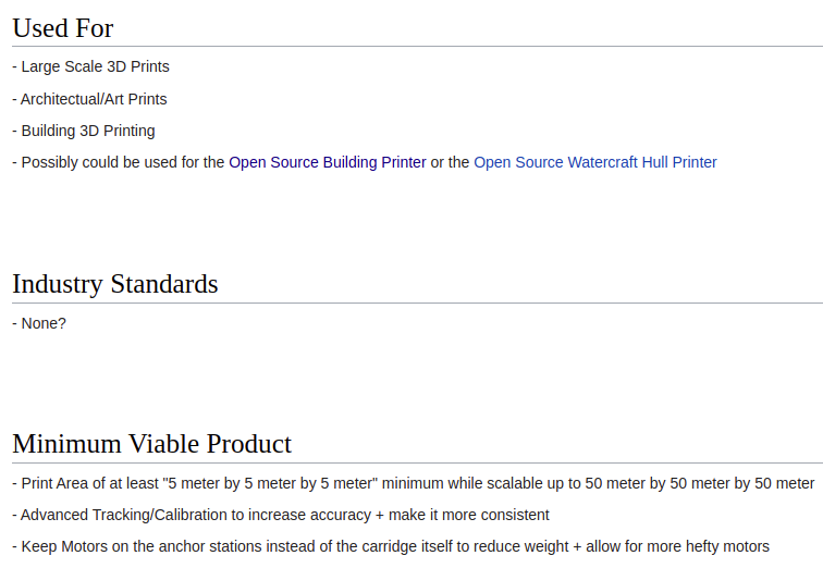
Open Source Ecology seemed to think that Hangprinter was already used for for 3d printing of buildings. They also believed that "Keep Motors on the anchor stations" was a prerequisite for a minimal viable product.
Note that Open Source Ecology and others who suggested locating the motors at the various anchor points back in 2014 to early 2018, in all the links are primarily laypeople trying to help out, without having "ordinary skill in the art" of cable-driven robotics. That's how obvious these ideas are to anyone with even a rudimentary understanding of Hangprinter.
Hangprinter's spools and motors weren't always placed in the ceiling. For example this one had a base station in one of the lower anchors:
What About the Guy Wires?
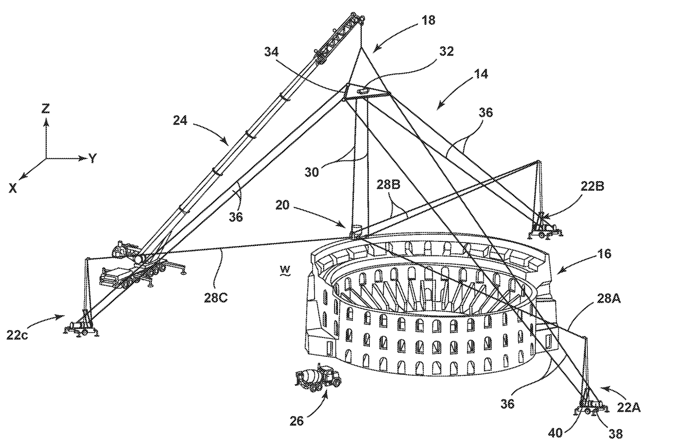
The patent in question describes guy wires going from the D-anchor (high-up) anchor down to the ABC-anchors (base stations) with tension in them to pull the D-anchor downwards and outwards in at least three directions and hence stabilizing the D-anchor. See, for example, lines 36 in Fig 4 from their patent, near the top of this web page.
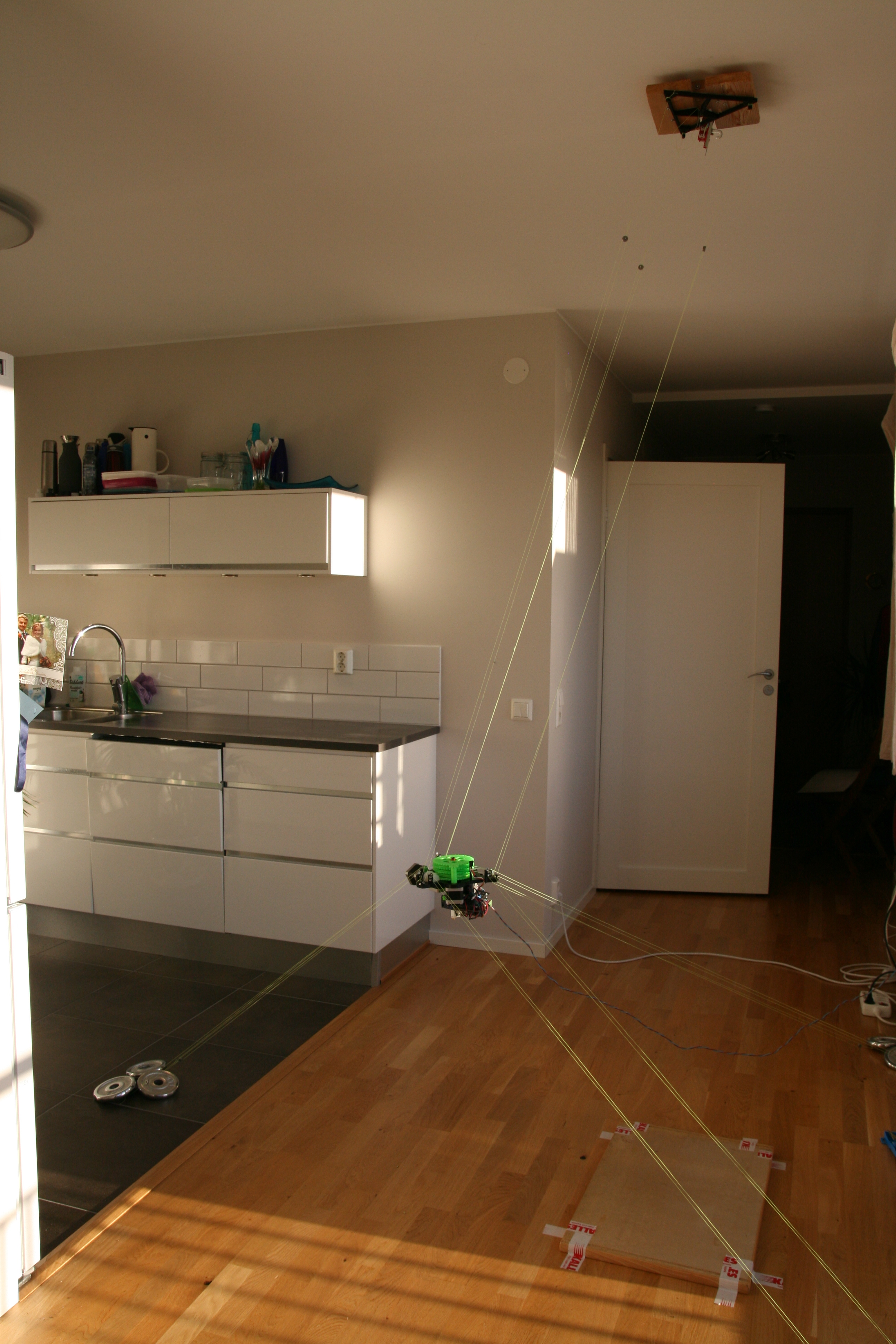
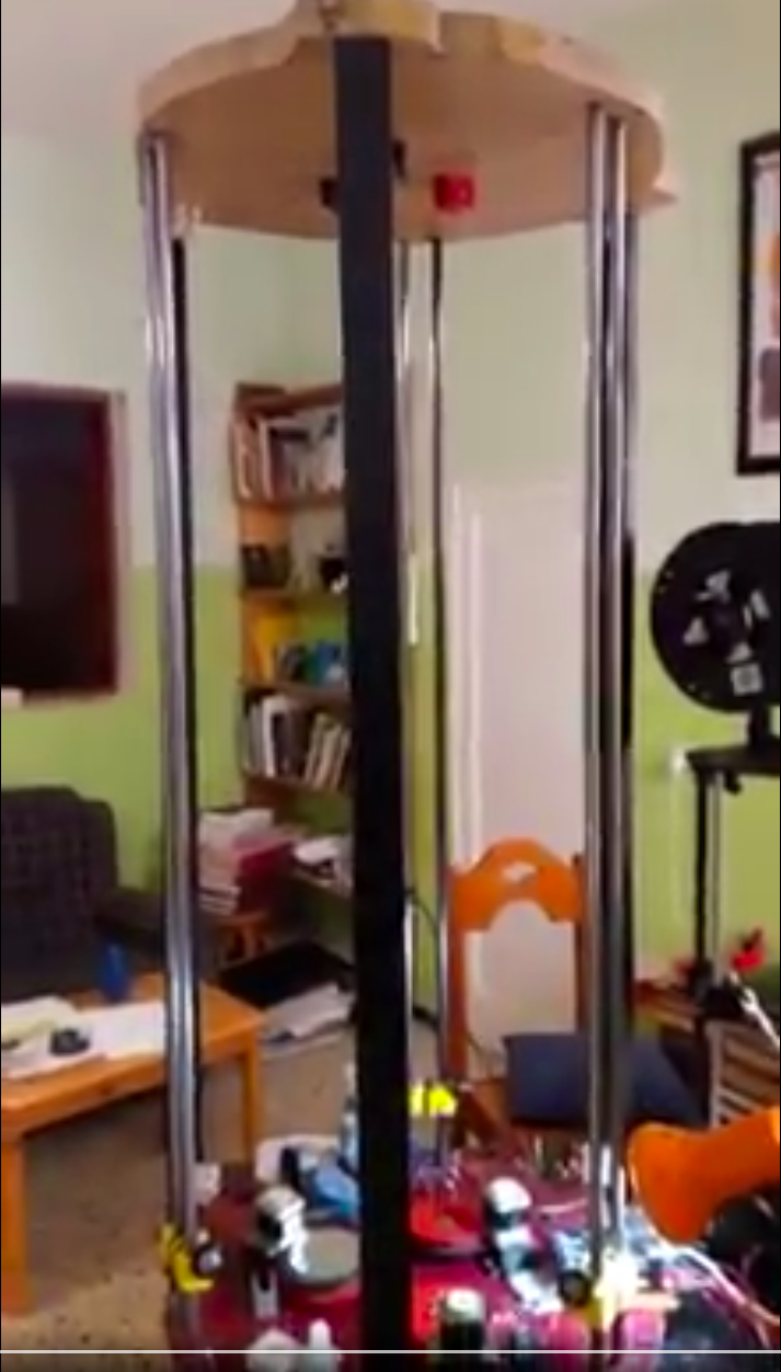
We have never used the terms "guy-wire" or "suspension wire" much in the Hangprinter community. However, we've had lines going between the D-anchor and the lower anchors, just like guy wires would, since April 2017. See, for example, the video posted at the top of this article or this image published on December 7, 2017:

Although Hangprinter's guy wires are rerouted to transmit motion forces to the end effector, these lines also do similar guy-wire pulling as the guy wires mentioned in the patent do.
Some might believe that the SkyBAAM's guy wires would be different because they would have constant tension. But in fact, the SkyBAAM's guy wires would not have constant tension during operation. The tension in the SkyBAAM's guy wires would vary greatly depending on variation in the pulling force from above and depending on the end effector's position at any given time. Let me explain.
The SkyBAAM's end effector connects to the D-anchor (highest anchor), where the guy wires are also connected. Any force in the D-wires going to the end effector will have to be canceled by opposite forces from the crane and the guy wires to keep the top anchor stationary. Forces from the D-lines will be changing all the time during operation.
Hangprinter's guy wires also experience changing tension depending on the end effector's position, but there will be some tension in them at all times during operation. So even though it might look like Hangprinter doesn't need guy wires, it does have them as part of its dual-purpose line routing configuration (in its most common version 3 embodiment).
The conceptual difference between the SkyBAAM's guy wires and Hangprinter's guy wires is only superficial if there's any difference at all.
But The Adjustable Guy Wires Then? What About Them?
From the patent in question:
"The guy-wires 36 can be adjustably extended from the cable winders 38 and retracted back on the cable winders 38."
This quote, combined with assumed adjustability of the crane's top wire length, means that "some embodiment of" the SkyBAAM might have a top anchor that is as movable in 3d space as its end effector (or maybe even more movable if that embodiment happens to have the stationary end effector feature described in the patent, but again, let's assume that's not the case).
The patent in question patent, therefore, covers the idea of a nested Hangprinter, or in other words, "one Hangprinter inside another".
That is, a Hangprinter that has its high anchor point attached to another Hangprinter's end effector. That sounds like a delightful combination of useless and incredibly inventive to me.
However, the Hangprinter community had already discussed this exotic idea publicly before the patent's filing date:
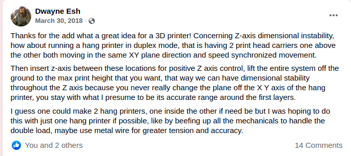
But SkyBAAM is Easily Transportable! Hangprinter Doesn't Even Have a Frame, It Requires Pre-existing Structures, No?
No. Hangprinter has always been "build a frame if you need one". What we did (and still do) at trade shows and such was the most basic and cheap thing, a tetrahedron out of two-by-twos:
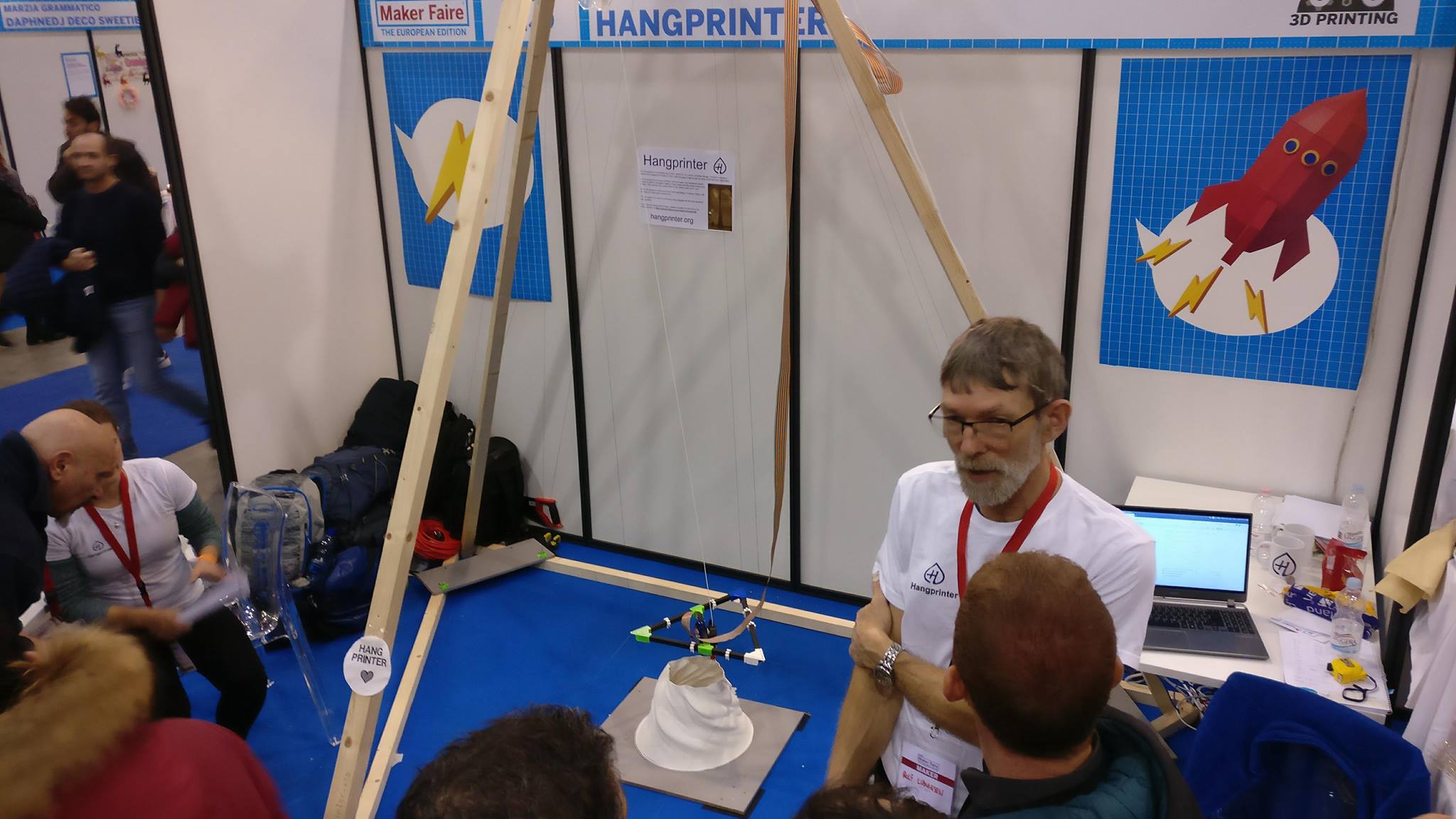
Most people can manage to create four stationary points where they want them, even without detailed instructions. Some design non-trivial full-blown frames for themselves, like this portable one:
But I Never Give Up! SkyBAAM Has A Hoisting Mechanism For Its Top Anchor. Hangprinter Did Not!!!1
I encourage you to check out, for example, what Alex Benz and the others at The Marietta Makers Station in Atlanta, GA, were doing in 2017:
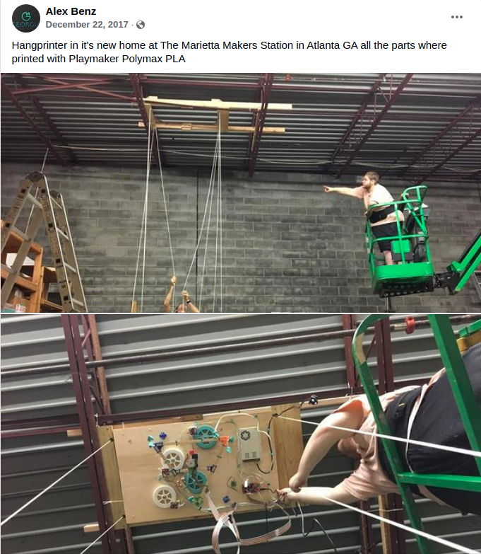
Getting the high anchor up is a very situation-dependent problem that Hangprinter users need to solve for themselves, which is why it's not included in the Hangprinter documentation. Surprisingly, the most obvious one ("use a crane") is the only one to have gotten patented so far.
But The UHMWPE Wires Then? Does Hangprinter Have Them?
Yes. Hangprinter has never used anything else. See, for example, this Bill Of Materials List from December 9, 2015.
Ok, so we've been having some fun looking at the hardware. Since we possess an ordinary skill in the art of cable-driven robotics and 3d printing, we know that we also need to look at source files and firmware.
We must dive deeper and ask questions like:
But Was The Repo Publicly Available?
The general public has continuously had access and usage rights to the repo since December 15, 2014, including April 13, 2018.
Information about how popular and well-known the repo was on April 13, 2018, can be found using archive.org, also known as Wayback Machine.
Here's how github.com/tobbelobb/hangprinter looked on June 26, 2017:

The image shows that the repo had 77 watchers, 248 stars, and 49 forks. Those are high numbers for a cable-driven robot. The 49 forks mean that at least 49 people have copied Hangprinter's source files as the basis for their own cable-driven robot builds.
The license in the repo allows and encourages such copying. Hangprinter was the most popular and widely known basis for cable-driven robot development in 2017 and 2018.
Very Basic Inverse Kinematics
Although the patent doesn't mention kinematics transforms in detail, I will go through Hangprinter's briefly here to make the case that Hangprinter could do a superset of the effector movements that the authors describe in the patent.
Therefore, the anchors can be placed at arbitrary positions around the print volume, and adding more of them is easy. Adding pure "tension control" lines requires no firmware changes at all.
But The SkyBAAM Moves Its Lower Anchors Upwards During Print. How Could Hangprinter Do That?
Yes. We touched upon this subject earlier, but let's explain how Hangprinter's firmware supported this.
See the gcode M665 in the firmware. A Hangprinter operator can use it during print to configure new anchor locations.
The values of anchor_A_z, anchor_B_z, and anchor_C_z in the code excerpt above
describe the z-positions of the three typically lower placed anchors (the A-, B-, and C-anchors).
These three values and all the other anchor position values, can be changed mid-print, with M665,
as evidenced by the widely covered 2017 tall tower print.
I repost the video here to save you from scrolling back.
All of these firmware features were being merged into the world's most used 3d printer firmware at the time, called Marlin Firmware, in a public merge thread (similar to a forum thread) that was open for anyone. This means Hangprinter was becoming an integrated and widely available type of 3d printer at the firmware level at the time before April 13, 2018.
A comment on the changes required to make low anchors move continuously upwards during print. Please refer to the source code figure above to understand what I'm talking about here.
The three terms similar to sq(anchor_ABC_z - cartesian[Z_AXIS]) would need to be swapped out with a constant value.
The three new motors, those lifting the ABC-anchors, let's call them Q, P, and R, would get their new positions calculated like this:
delta[Q_AXIS] = cartesian[Z_AXIS]
Making the anchor movements continuous is a minimal change to the kinematics. It is already in commercial use in February 2022; see bloft.fi (not prior art).
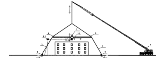
Another way of "lifting anchor points continuously during operation" that was prior art on the patent's filing date is to span up a giant 2d frame, like this:
But The Balloon Idea? The Authors Mention Swapping The Crane For A Balloon In The Text. Can They Keep That Idea For Themselves?
It's a fun idea, but they are not the first to describe it. It has been discussed in the Hangprinter community. However, the Hangprinter Community wasn't first either.
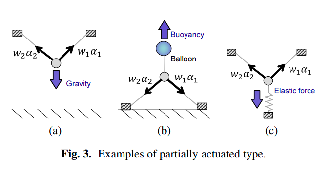
The idea is evident to anyone with ordinary skills in the art of parallel robotics. It's even described in textbooks about parallel robotics:

The whole idea of a partly actuated cable-driven robot, whether the external force comes from a balloon, gravity, a spring, or even a "tension-control base station" is not new in the world of cable-driven robotics.
Non-Hangprinter Prior Art That Went Unreferenced
I've already mentioned the SkyDelta but I repost the video here to save you from scrolling back.
SkyBAAM shares the first half of its name with three pre-existing and very similar robots:
- SkyDelta (2013),
- SkyCam (the 1980s),
- Sky Printer (2014).
But it's not only Hangprinter and the Sky-somethings that went unreferenced by the patent in question. A related patent is also missing.
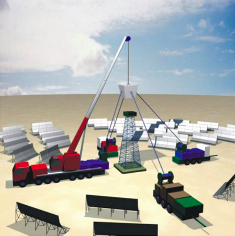
A quick Google search "cable-driven 3d-printer construction" gives us another high-profile that went unreferenced. This one is from Advanced Architecture of Catalonia's (IAAC's) on site robotics project in 2017. Except for not using Hangprinter-like anchor-configuration, it's identical to SkyBAAM.
A search on Google Scholar gives yet another unreferenced example. It's presented unceremoniously as a generic example of cable-driven robot usage in a scientific paper. It points to how prominent the crane+base station concept is and that it was already in use for precise positional control, long before 2018:
Postludium
Adding together the current day (February 7, 2022) view counts from three popular Hangprinter-related Youtube videos published before March 30, 2017, gives a combined view count of 242041.
I think every person following news channels covering 3d printing would have heard about Hangprinter on April 13, 2018, including its obvious potential to scale up. All these people know that Hangprinter is open source. They know they can use Hangprinter however they like. They also know nobody can patent Hangprinter or any other open source hardware project.
I'm happy to observe that central inventors in the 3d printing industry say that Hangprinter could be used to invalidate the patent (not prior art).
Why I Wrote This Prior Art Presentation
I think the patent in question covers well-known and established know-how and some demonstrably obvious and frequent ideas from the period before the filing date. Nothing in the patent fulfills the criteria of being non-obvious to a person having ordinary skill in the art of cable-driven robotics or 3d printing, not now, and not during the period before the filing date. In short, I think patent US 11230032 should be withdrawn or invalidated.
Appendix
Safety Concerns
First of all, the telescoping flagpole (Fig 3 in the patent in question) is a dangerous approach, given its considereable risk of falling over. Apart from damaging health and property, it would hurt Hangprinter's reputation in the same way as self-igniting commercial clones hurt the reputation of Prusa and other RepRaps (not prior art).
The mobile crane with its arm over the Colosseum also risks falling over very quickly. Something like what's shown in Fig 3 in the patent in question should never be built in practice. Please consider safety before scaling up Hangprinter.
A More Sensible Approach To Designing Anchor Points For Construction Work With Hangprinter. Alternative To SkyBAAM's Single Crane And Telescoping Flagpoles
A better base station would be any old mobile crane since they're already available and not restricted to purely vertical motion. Why not a $23000 electric spider drive crane? (not prior art), or a simpler car winch size (not prior art) for smaller jobs?
Maybe the most practical thing would be three or four (or even more) spider crane-like vehicles lifting the D-anchor together, with their lifting arms connected at a single high point, forming a polyhedron shaped like a regular pyramid (not prior art). The lift arms would not have to be very stiff because of the self-supporting properties of pyramid shapes.
The spider crane-like vehicles could also have cable winches on board, close to the ground level. If their lift-arms were, in fact, telescoping or foldable linear rails, then the lower anchor points could slide up along the crane-arm-rails during operation if necessary to avoid suspension cables potentially interfering with the unfinished 3d print.
Simple attachment points along the crane arm would be simpler and easier to implement. Blocks at several attachment points could reroute lower (ABC) suspension cables. Such rerouting would require manual intervention and maybe manual lifting during operation.
The crane-arm-rails or attachment points along the crane-arm would increase the stiffness requirements on the crane-arms considerably and should be made optional or be limited to a low enough max height not to risk the crane-arm breaking during operation.
PS! Please don't patent my ideas.
You know the rules, and so do I.
- tobben
