Winches can be imprecise for many reasons.
Spools typically store irregularities as well as part of the line iteself.
Buildup is a basic type of irregularity. It can change spool radius in unpredictable ways via crossing layers, buried turns,
and pile-ups (most often at the flanges).
There's always trapped slackness/tightness along the stored line, since there's friction between the spool and the line. These
are small irregularities, but they're real and almost unavoidable during normal use.
Sometimes there are also larger irregularities, like "bubbles", trapped loose loops, or other variations of tangling.
There are many strategies for trying to enforce precision by reducing or eliminating irregularities, or to measure and
compensate for them.
1: Reduce
Make windings stay in place by always enforcing a minimum tension. This can be achieved with spring, weight or other stored
energy driven mechanics, or with clever sensing+motor control.
Make tightness and tangles on the spool sort it self out by making the line and the spool itself stiff and smooth. If line
would be possible to pull of a winch spool completely frictionless, then tangles would have fewer places to hide on that spool.
Keep slackness off the spool by carefully enclosing the spool and/or push the line onto the spool with rollers. Make it so
that the slack has nowhere to go inside the winch and is forced to accumulate outside the winch.
2: Eliminate
Make buildup impossible by using large radius spool and thin and/or short line.
Avoid crossing layers and pile-ups by carefully controlling where line is laid down on the spool. This can be achieved with
(Lebus) grooves that guide the line and/or a translating spool and/or a translating line guide.
3: Compensate
Allow buildup to happen but try to predict by building a physics model, and use it to calculate compensation amount it in
firmware.
Make buildup more predictable by using belts, which is basically a flat line with teeth. It can stack windings neatly on top
of itself, like having buildup, but in a perfect spiral shape. There's pile-up but there's no crossing layers of buried turns.
4: Measure and Compensate
Place an encoder in front of the spool or measure line length in some other way. This lets you live tune compensation parameters
or act directly on how much line is measured to have gone on/off the spool.
Measure or predict tension in each segment of each line that enters a spool. Can be used to compensate for trapped slackness/tightness.
Strategy Combinations
1.1
1.2
1.3
2.1
2.2
3.1
3.2
4.1
4.2
HP4
✓
✓
~
✓
Maslow
✓
✓
✓
Industrial
✓
✓
✓
✓
Experiments
✓
Target
✓
✓
✓
~
✓
✓
✓
✓
Hangprinter has been doing 1.2, 2.1, 3.1. The HP4 also did a bit of 1.3.
Our beloved strategy 2.1 was lost when the thin line snapped and had to be replaced by more robust and reliable, and
therefore thicker, lines.
We can get some of it back through careful parameter choice, but we need other strategies as well.
The Maslow 4 does 1.1, 3.2, and 4.1.
Typical industrial winches do 1.1, 2.2 and 3.1 or 4.1 depending on the precision requirement.
I'm very impressed with the Maslow 4's combination of strategies.
It looks very elegant for its use case; 2D movement with weight, friction and low speeds.
Belts are less practical for a 3D robot like Hangprinter with lots of lines in lots of directions.
Probably still doable but not as perfect of a fit as it is for the Maslow 4.
My RefWinch experiments so far have tried to add 2.2 to HP4's old 1.2, 1.3, 3.1 combo.
What if we borrow 1.1 and 4.1 as well? We abviously also want a bit of 2.1 back.
Belts are outside the scope of the RefWinch project, but nothing's preventing us from doing a bit of 4.2.
I think 1.1, 1.2, 1.3, 2.1, 2.2, 3.1, 4.1, and 4.2 should all be combined into the reference. That is, every strategy
that allow round lines.
Individual users can remove the strategies they don't need or can't afford,
similar to how HP4 was designed as closed-loop but many users couldn't afford that, and built it as open-loop instead.
Here are my experiments so far:
- tobben
Torbjørn Ludvigsen
Winches can be imprecise for many reasons.
Spools typically store irregularities as well as part of the line iteself.
Hangprinter RefWinch Design Document
21-5-2026
Goal and Purpose (why do we do the RefWinch Project?)
We need good winches.
We also need a known baseline.
In this project the baseline winch is a wide, belt driven tube.
Winches dictate the price, performance, and complexity of the full machine.
Previous Hangprinter winches were low on performance.
They forced users to accept line buildup, which is a very opinionated choice, trading away performance for low price
and low complexity.
The RefWinch Project should
Find out what baseline performance we're competing against.
Measure how much better than that we get with our design decisions.
This is roughly where I expect the "belt driven rotating tube" baseline to end up. It's hard to get cheaper or less complex.Where we should aim with RefWinch, adding a fixed entry/exit point and preventing buildup pushes characteristics in a new
direction.
Requirements (what exactly must the refwinch be able to do?)
Constant transmission ratio (no buildup).
Known/fixed cable entry/exit point.
Cheap. Motor+driver+line should make up at least 80% of the total price per winch. Motor+driver+line will cost ~40 USD so
the rest should not cost more than ~10 USD.
Back-driveable, smooth transmission. It must be usable in torque mode both winding in and winding out.
Fairly rigid.
Support for at least 1.5 mm thick lines
Capacity of 12 m of line.
Compatibility with a wide range of stepper and BLDC motors around the Nema17 size.
Small enough to run on a desktop machine, big enough to run a room-size machine.
Robust against vibrations, resonances, highly dynamic motor movements, shaking motors, fast accelerations/decelerations. We
want to print tiny infill fast.
Main deployed lines (the line deployed and retrieved by the winch): Compatible with round UHMWPE lines. Note: internal drivetrain
mechanism may use any transmission method.
Nice-to-Haves
Somewhere to connect a load sensor.
Emergency release mechanism/behavior to save people and hardware in extreme load situations.
Silent operation.
Work equally well if mounted vertically or horizontally.
Fully enclosed line path, so line can't ever jump loose and wrap around motor shaft.
Easily and rigidly mountable on a standard OpenBeam.
Fit deep into a corner of a room while line/exit point still pointing right towards middle of room.
Somewhere to route connectors/cables so it looks nice and tidy.
Main deployed line: Compatibility with non-UHMWPE lines, flat lines, syncromesh cable, as well as belts.
Non-Requirements (what is often optimized for in similar projects that we don't care about here?)
Backlash. We will only ever load the spool from one direction.
Back-and-forth layering.
Support for belt instead of line around the drum.
Low weight.
Functional requirements/solutions (how do we want it to achieve that?)
Probably by utilizing one of the following principles:
Translating-Motor Design
Rototranslating-Drum Design
Spline Winch
Spooling-Helper Design
See this paper for definitions of the four principles.
Validation (how to know if we got what we wanted?)
Can it:
Pull in tight line?
Pull in loose line?
Feed out tight line?
Feed out loose line?
Does line fall off the spool during setup or operation?
Is it cheap enough?
Does it fail often? (cable spagetthi, friction locking, parts breaking or similar)
Can we service the spool, eyelet and other parts without unthreading the line?
Does it take up our time?
The winch should just disappear from our minds after testing and installation. We should not have to worry about it
much.
- tobben
Torbjørn Ludvigsen
We need good winches.
We also need a known baseline.
In this project the baseline winch is a wide, belt driven tube.
Hangprinter Reference Rig Design Document
21-5-2026
Goal and Purpose (why do we make refrig?)
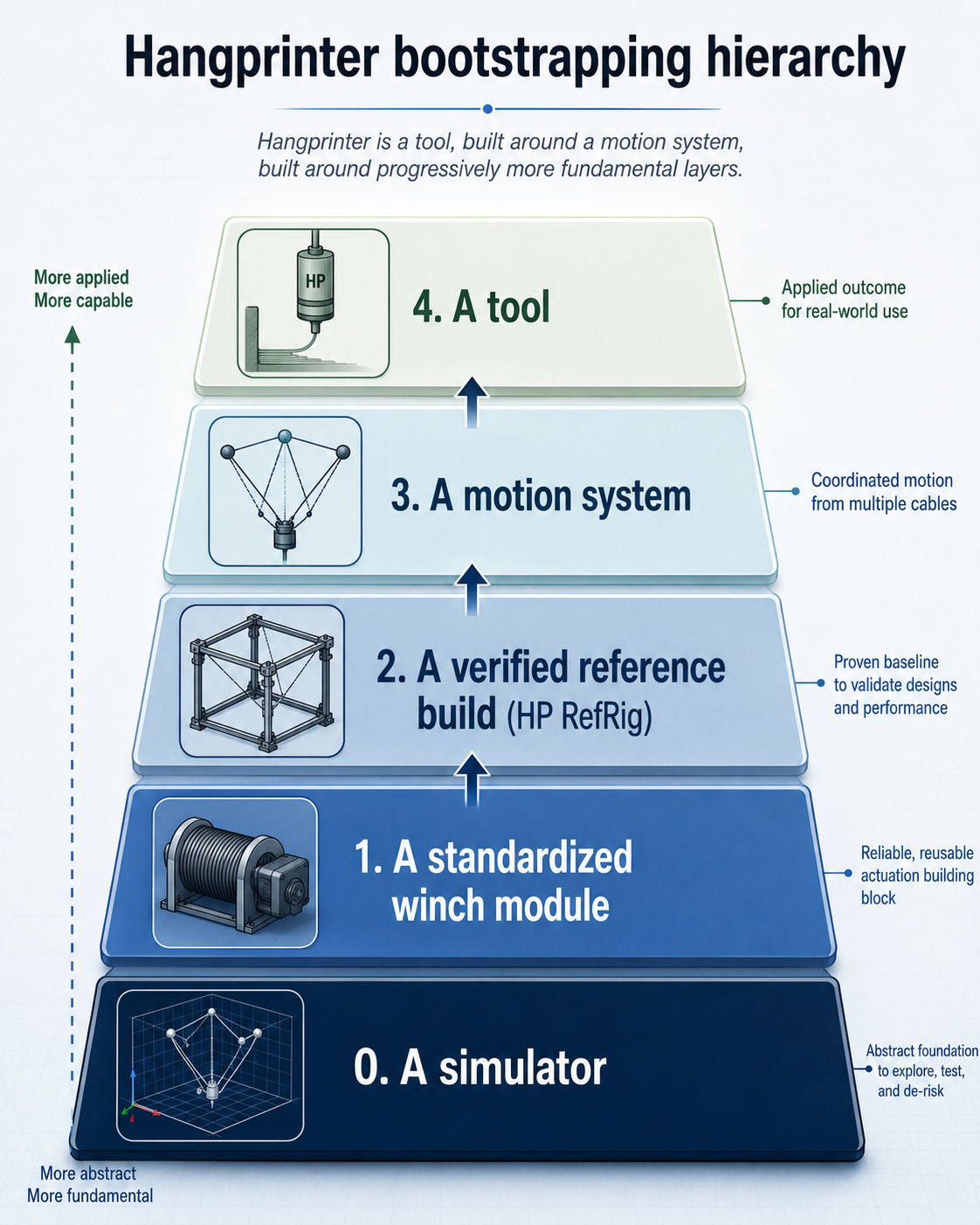
RefRig is a Reference Rig for the Hangprinter Project.
It's step 2 in the Hangprinter Bootstrapping Hierarchy:
RefRig is everybody's first physical build and the place where new features get added first.
It's therefore also the most documented build and the place where all features are expected to work.
It's not a full-size Hangprinter, CDPR, or the best 3D printer in general.
But for the Hangprinter Project it's both the minimal viable machine and every larger machine's pre-flight test bed.
That makes it our biggest support, verification, and documentation category.
Up until and including the RefRig step we can have:
Versioned BOM
Known-good config
Build instructions that include everything
Acceptance tests
Ready-built digital twin
A hardware platform where autocal or other special software features are expected to work first
RefRig represents all the things users should do before they start scaling, improving, etc.
Stakeholders and User Stories (who do we design for and what do they want?)
Me (Torbjørn) as a developer want
Somewhere to mount and test RefWinches, who are designed in a separate project, but almost always used together with RefRig.
A malleable, configurable, small and cheap frame for a cable driven robot, that captures the physical phenomena we see in
full scale Hangprinters and other CDPRs.
A minimal but realistic end-to-end physical test rig for debug, diagnostics, experiments, etc.
Support for a wide range of firmwares, motor types, electronics boards etc
Support a wide range of sensors that are easily attached, cable routed, removed.
Me (Torbjørn) as a maintainer want
Clear bounds for what's supported and what's not, and
Easy to understand questions with easily interpretable data attached.
Newcomers to Cable Driven Robotics want
Something cheap, structured, and well thought out.
An experience with emphasis on basic principles.
A path from "I don't understand" to "I can build, test, calibrate, and reason about this machine."
Early wins and clear failure modes.
Not to have to buy private consulting hours just to get something moving.
Builders / testers / field techs want
Repeatable assembly steps.
Clear pass/fail tests.
Known-good configs and diagnostics.
Problem categorization (mechanical, electrical, firmware, calibration, documentation, etc).
Doc writers / teachers / workshop organizers want
A stable reference object to teach from.
Exercises, tests, diagrams, and failure examples that do not change every week.
A machine that can be used in makerspaces and schools as demonstration.
Kit makers / suppliers want
A versioned BOM and standard interfaces.
To know which parts matter and which parts can vary.
Well defined tolerances, other requirements and tests for each individual part. Preferrably test rigs for everything that
matters.
A way to say "this kit/build/module passes the RefRig tests".
Salespeople/funding hunters want
Something that looks clean, is easy to travel with, easy to understand, easy to show quickly.
Physical proof that Hangprinter is not just an idea.
A machine that supports the basic pitch: open, cheap, reliable precision motion over large volumes.
Requirements (what exactly must the refrig be able to do?)
Fit on a desktop.
It must be a real working 3D printer.
Have known anchor positions so autocal results can be quality controlled.
Compatibility with both buildup and no-buildup versions of RefWinch
Rigid and robust with no experimental solutions, ie as standard a frame as possible.
Feel "minimal", "natural", cheap and easily sourced so as to not tempt users to add their own changes.
Be rigid enough to not deform in event of being knocked over, or if all motors pull with all their power for a few seconds.
Give us debugging data enough for verification and coparison with hp-sim5 digital twin.
Functional requirements/solutions (how do we want it to achieve that?)
Square aluminum beams such as OpenBeams. Preferrably a ready-made skeleton of another 3d printer such as RatRig, Voron, Bambulabs
or similar. This lets us piggy-back on accessories such as
spool hoders,
LED lights,
enclosures,
electronics mounting racks
etc.
Use RefWinch, the standardized winch module
Documentation as part of the machine
RefRig is not finished unless its instructions, tests, and troubleshooting docs are finished.
Docs should explain not only how to build it, but how to know which subsystem failed.
Support questions should be routed through the test ladder where possible.
RefWinch must continue the Stepwise Build and Test Ladder from the RefWinch Project. The Ladder should be defined seperately
somewhere else but it will be similar to:
Test electronics alone.
Test one winch alone.
Test all winches without full machine load.
Test geometry/anchor measurements.
Test basic motion.
Test calibration.
Test repeatability.
Test edge cases and failure modes.
RefRig does not specify what electronics or firmware to use, but data collection (log interfaces and structure) are defined
as part of the RefRig.
Expected Developments but Not Part of RefRig v1
Run both ReprapFirmware and Klipper, including all features, such as
Extruder
Bed probe
Accelerometer/input shaping
Support all the physical configurations that firmware supports:
HP3 (three low anchors, one central high anchor, no gearing)
HP4 (same anchor placements, lots of gearing)
Skycam (four high anchors)
Cubecorners (eight anchors)
Slideprinter (three or four low anchors, no high anchors).
Run hp-sim5's autocal succesfully
Simulator-to-physical workflow
Define the RefRig in hp-sim5.
Run simulated conformance tests.
Run the same or equivalent firmware/motion commands on physical RefRig.
Compare logs and measured behavior.
Use differences to improve simulator, firmware, calibration, and hardware.
ROS2 is a stretch goal.
Data collection could be rosbags and we could piggyback on the ROS2 ecosystem, but that's not a requirement.
Sim-real connection/orchestration could also be handled by ROS2.
Logging and diagnostics
Make it easy to collect calibration data.
Make it easy to run active calibration experiments.
Store diagnostic logs in a predictable format.
Prefer tests that produce numbers, plots, logs, or pass/fail results.
ROS2 is a stretch goal here as well. The whole autocal procedure might go via some ROS2 interface?
RefRig should suggest a standard camera and standard camera placements for video debugging, so we have the opportunity to
easily create videos where we can know what we're looking at, from what angle, in all support requests.
Validation (how to know if we got what we wanted?)
Primary:
It works. Prints Benchys and stuff.
It is considered the reference.
Secondary:
It works measurably similar to its simulated twin.
It's not avoided or postponed by builders or learners.
Builders build RefRig faster and cheaper than they would have built a full machine.
Builders get knowledge, learning, understanding that affects their full build.
Its pass/fail tests are used and actually catches hw/assembly bugs.
Builders go ahead with the full build afterwards (if that was their plan/goal).
It's fun.
It's not annoying.
Harder to know but relevant if we could:
It gets new people in the door.
Does RefRig enable builders that would otherwise not build? ie, quantitatively:
Do we see an increase in the number of Hangprinter builds (counting just full builds)? and qualitatively:
Are the full builds we see better in terms of print quality, and uptime? and even more qualitatively:
Are the builders happier than before? Are they prouder? Do we see them post more on Discord and other places?
- tobben
Torbjørn Ludvigsen
RefRig is a Reference Rig for the Hangprinter Project.
It's step 2 in the Hangprinter Bootstrapping Hierarchy:
Everything on this homepage, except those videos who are published via Vimeo or Youtube, is licensed under the Gnu Free Documentation License.
The videos published via Vimeo or Youtube are also licensed via Vimeo or Youtube.